

Answered step by step
Verified Expert Solution
Question
1 Approved Answer
Unit tester file. C++ preferred. //Bring in unit testing code and tell it to build a main function #define DOCTEST_CONFIG_IMPLEMENT_WITH_MAIN //This pragma supresses a bunch
Unit tester file. C++ preferred. //Bring in unit testing code and tell it to build a main function
#define DOCTEST_CONFIG_IMPLEMENT_WITH_MAIN
//This pragma supresses a bunch of warnings QTCreator produces (and should not)
#pragma clang diagnostic ignored "-Woverloaded-shift-op-parentheses"
#include "doctest.h"
//Use Approx from doctest without saying doctest::Approx
using doctest::Approx;
//Include your .h files
#include "Pin.h"
#include "NotGate.h"
#include "TwoInputGate.h"
#include
#include
using namespace std;
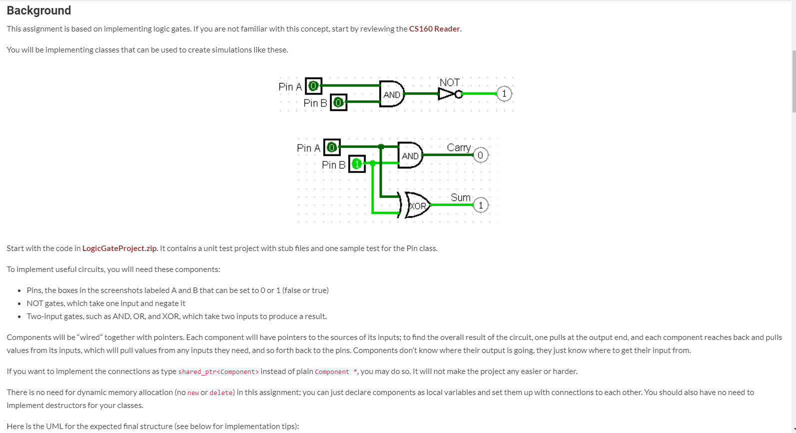
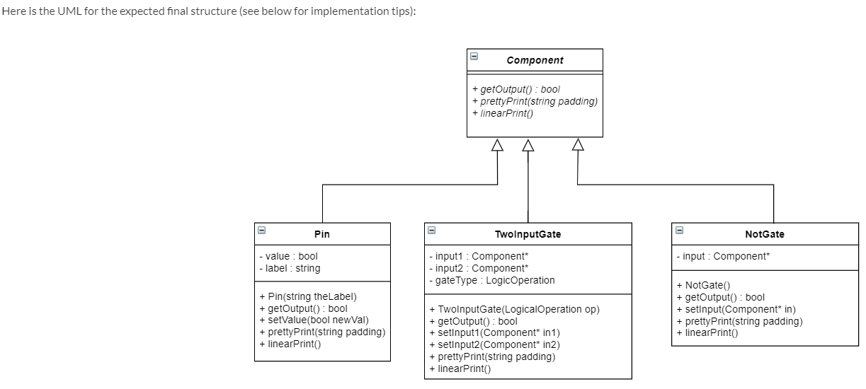
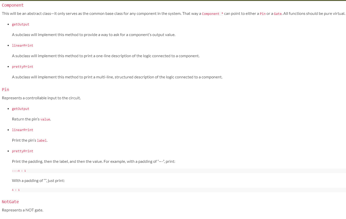
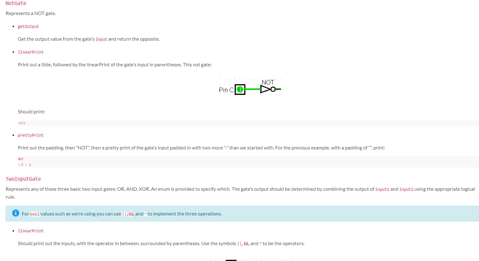
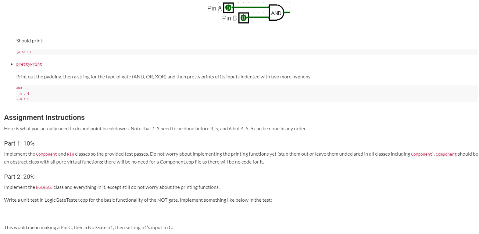
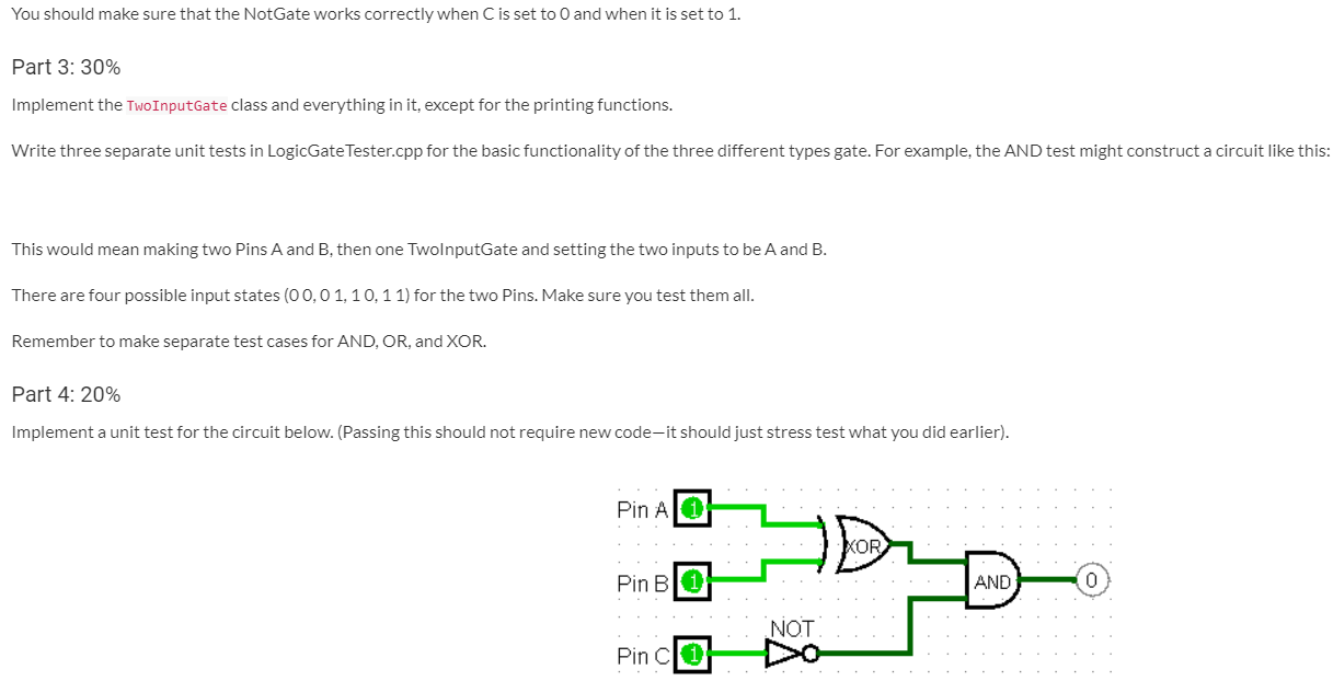
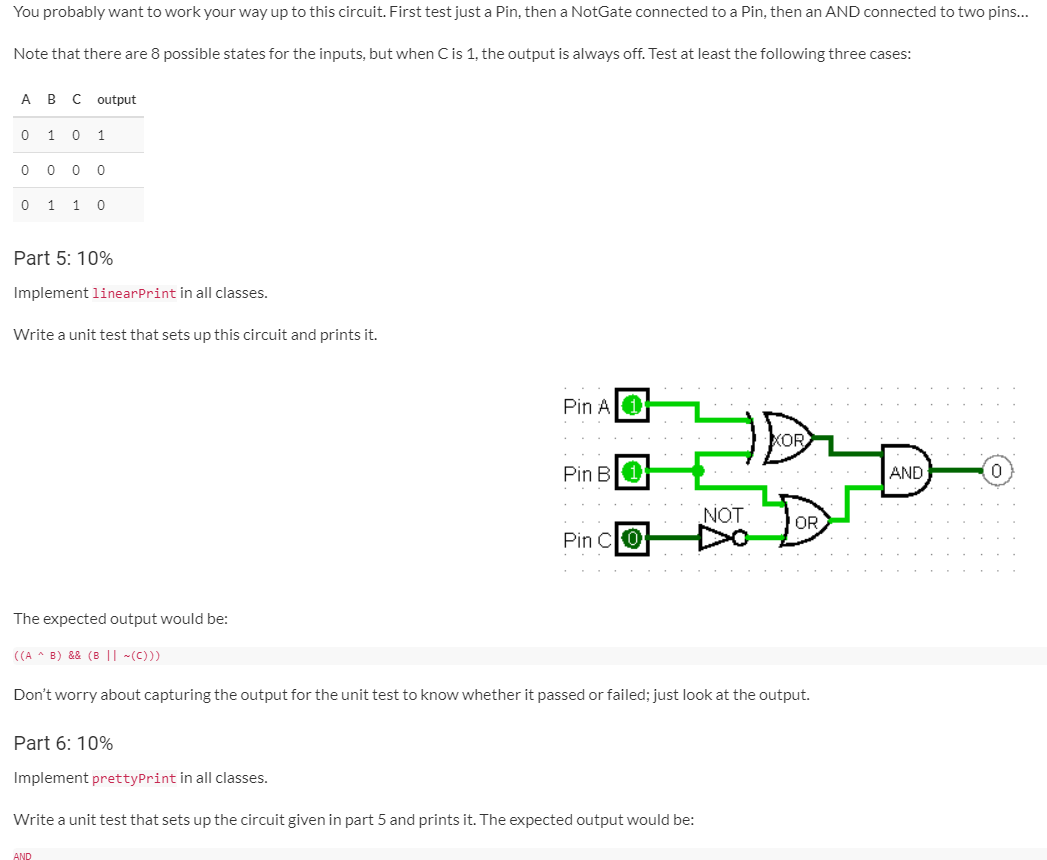
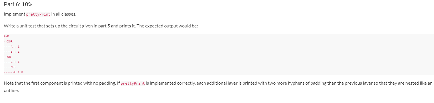
TEST_CASE( "Components/Pin" ) { coutPin a("A");a.setValue(false);REQUIRE(a.getOutput() == false);a.setValue(true);REQUIRE(a.getOutput() == true);}Background This assignment is based on implementing logic gates. If you are not familiar with this concept, start by reviewing the CS160 Reader. You will be implementing classes that can be used to create simulations like these. Pin ATO NOT AND Pin BIO Pin AIO Carry AND Pin B1 XOR Sum 1 Start with the code in LogicGate Project.zip. It contains a unit test project with stub files and one sample test for the Pin class. To implement useful circuits, you will need these components: Pins, the boxes in the screenshots labeled A and B that can be set to 0 or 1 (false or true) NOT gates, which take one input and negate it Two-input gates, such as AND, OR, and XOR, which take two inputs to produce a result. Components will be "wired together with pointers. Each component will have pointers to the sources of its inputs; to find the overall result of the circuit, one pulls at the output end, and each component reaches back and pulls values from its inputs, which will pull values from any inputs they need, and so forth back to the pins. Components don't know where their output is going, they just know where to get their input from. If you want to implement the connections as type shared_ptrinstead of plain component *, you may do so. It will not make the project any easier or harder. There is no need for dynamic memory allocation (no new or delete) in this assignment; you can just declare components as local variables and set them up with connections to each other. You should also have no need to implement destructors for your classes. Here is the UML for the expected final structure (see below for implementation tips): Here is the UML for the expected final structure (see below for implementation tips): Component + getOutput(): bool + pretty Print(string padding) + linearPrint) - Pin TwolnputGate NotGate - input: Component - value : bool - label : string - input1 : Component* - input2: Component - gate Type : LogicOperation + Pin(string theLabel) getOutput(): bool + setValue(bool newVal) + pretty Print(string padding) + linearPrint) + NotGate() + getOutput(): bool + setInput(Component* in) + pretty Print(string padding) + linearPrint + TwolnputGate (LogicalOperation op) + getOutput(): bool + setlnput1(Component* in 1) + setinput2(Component* in2) + pretty Print(string padding) + linearPrint Component This will be an abstract class-it only serves as the common base class for any component in the system. That way a Component * can point to either a Pin or a Gate. All functions should be pure virtual. getOutput A subclass will implement this method to provide a way to ask for a component's output value. linearPrint A subclass will implement this method to print a one-line description of the logic connected to a component. prettyPrint A subclass will implement this method to print a multi-line, structured description of the logic connected to a component. Pin Represents a controllable input to the circuit. getOutput Return the pin's value. linearPrint Print the pin's label. prettyPrint Print the padding, then the label, and then the value. For example, with a padding of "_", print: ----A: 1 With a padding of "", just print: A: 1 NotGate Represents a NOT gate. NotGate Represents a NOT gate. getOutput Get the output value from the gate's input and return the opposite. linearPrint Print out a tilde, followed by the linear Print of the gate's input in parentheses. This not gate: NOT Pin cl 1 Should print: prettyPrint Print out the padding, then "NOT", then a pretty print of the gate's input padded in with two more "-" than we started with. For the previous example, with a padding of ", print: NOT --C: 1 Two InputGate Represents any of these three basic two input gates: OR, AND, XOR. An enum is provided to specify which. The gate's output should be determined by combining the output of input1 and input2 using the appropriate logical rule. For bool values such as we're using you can use ||, &&, and to implement the three operations. linearPrint Should print out the inputs, with the operator in between, surrounded by parentheses. Use the symbols 1.&&, and to be the operators. Pin Ali AND Pin BIO Should print: (A && B) prettyPrint Print out the padding, then a string for the type of gate (AND, OR, XOR) and then pretty prints of its inputs indented with two more hyphens. AND --A: --Be Assignment Instructions Here is what you actually need to do and point breakdowns. Note that 1-3 need to be done before 4,5, and 6 but 4, 5, 6 can be done in any order. Part 1: 10% Implement the Component and Pin classes so the provided test passes. Do not worry about implementing the printing functions yet (stub them out or leave them undeclared in all classes including Component). Component should be an abstract class with all pure virtual functions; there will be no need for a Component.cpp file as there will be no code for it. Part 2: 20% Implement the NotGate class and everything in it, except still do not worry about the printing functions. Write a unit test in LogicGate Tester.cpp for the basic functionality of the NOT gate. Implement something like below in the test: This would mean making a Pin C, then a NotGate n1, then setting n1's input to C. You should make sure that the NotGate works correctly when C is set to 0 and when it is set to 1. Part 3: 30% Implement the Two InputGate class and everything in it, except for the printing functions. Write three separate unit tests in LogicGate Tester.cpp for the basic functionality of the three different types gate. For example, the AND test might construct a circuit like this: This would mean making two Pins A and B, then one TwolnputGate and setting the two inputs to be A and B. There are four possible input states (0 0,0 1, 10, 11) for the two Pins. Make sure you test them all. Remember to make separate test cases for AND, OR, and XOR. Part 4: 20% Implement a unit test for the circuit below. (Passing this should not require new code-it should just stress test what you did earlier). Pin A 0 XOR Pin B1 AND 0 NOT Pin C You probably want to work your way up to this circuit. First test just a Pin, then a NotGate connected to a Pin, then an AND connected to two pins... Note that there are 8 possible states for the inputs, but when C is 1, the output is always off. Test at least the following three cases: A B C output 0 1 0 1 0 0 0 0 0 1 1 0 Part 5: 10% Implement linearPrint in all classes. Write a unit test that sets up this circuit and prints it. Pin AO XOR Pin Bl 1 AND o NOT OR Pin CIO The expected output would be: (A - B) && (B || -(0))) Don't worry about capturing the output for the unit test to know whether it passed or failed; just look at the output. Part 6: 10% Implement prettyPrint in all classes. Write a unit test that sets up the circuit given in part 5 and prints it. The expected output would be: AND Part 6: 10% Implement prettyPrint in all classes. Write a unit test that sets up the circuit given in part 5 and prints it. The expected output would be: AND --XOR ----B : 1 --OR ----B : 1 ----NOT ------C: Note that the first component is printed with no padding. If prettyPrint is implemented correctly, each additional layer is printed with two more hyphens of padding than the previous layer so that they are nested like an outline. Background This assignment is based on implementing logic gates. If you are not familiar with this concept, start by reviewing the CS160 Reader. You will be implementing classes that can be used to create simulations like these. Pin ATO NOT AND Pin BIO Pin AIO Carry AND Pin B1 XOR Sum 1 Start with the code in LogicGate Project.zip. It contains a unit test project with stub files and one sample test for the Pin class. To implement useful circuits, you will need these components: Pins, the boxes in the screenshots labeled A and B that can be set to 0 or 1 (false or true) NOT gates, which take one input and negate it Two-input gates, such as AND, OR, and XOR, which take two inputs to produce a result. Components will be "wired together with pointers. Each component will have pointers to the sources of its inputs; to find the overall result of the circuit, one pulls at the output end, and each component reaches back and pulls values from its inputs, which will pull values from any inputs they need, and so forth back to the pins. Components don't know where their output is going, they just know where to get their input from. If you want to implement the connections as type shared_ptr instead of plain component *, you may do so. It will not make the project any easier or harder. There is no need for dynamic memory allocation (no new or delete) in this assignment; you can just declare components as local variables and set them up with connections to each other. You should also have no need to implement destructors for your classes. Here is the UML for the expected final structure (see below for implementation tips): Here is the UML for the expected final structure (see below for implementation tips): Component + getOutput(): bool + pretty Print(string padding) + linearPrint) - Pin TwolnputGate NotGate - input: Component - value : bool - label : string - input1 : Component* - input2: Component - gate Type : LogicOperation + Pin(string theLabel) getOutput(): bool + setValue(bool newVal) + pretty Print(string padding) + linearPrint) + NotGate() + getOutput(): bool + setInput(Component* in) + pretty Print(string padding) + linearPrint + TwolnputGate (LogicalOperation op) + getOutput(): bool + setlnput1(Component* in 1) + setinput2(Component* in2) + pretty Print(string padding) + linearPrint Component This will be an abstract class-it only serves as the common base class for any component in the system. That way a Component * can point to either a Pin or a Gate. All functions should be pure virtual. getOutput A subclass will implement this method to provide a way to ask for a component's output value. linearPrint A subclass will implement this method to print a one-line description of the logic connected to a component. prettyPrint A subclass will implement this method to print a multi-line, structured description of the logic connected to a component. Pin Represents a controllable input to the circuit. getOutput Return the pin's value. linearPrint Print the pin's label. prettyPrint Print the padding, then the label, and then the value. For example, with a padding of "_", print: ----A: 1 With a padding of "", just print: A: 1 NotGate Represents a NOT gate. NotGate Represents a NOT gate. getOutput Get the output value from the gate's input and return the opposite. linearPrint Print out a tilde, followed by the linear Print of the gate's input in parentheses. This not gate: NOT Pin cl 1 Should print: prettyPrint Print out the padding, then "NOT", then a pretty print of the gate's input padded in with two more "-" than we started with. For the previous example, with a padding of ", print: NOT --C: 1 Two InputGate Represents any of these three basic two input gates: OR, AND, XOR. An enum is provided to specify which. The gate's output should be determined by combining the output of input1 and input2 using the appropriate logical rule. For bool values such as we're using you can use ||, &&, and to implement the three operations. linearPrint Should print out the inputs, with the operator in between, surrounded by parentheses. Use the symbols 1.&&, and to be the operators. Pin Ali AND Pin BIO Should print: (A && B) prettyPrint Print out the padding, then a string for the type of gate (AND, OR, XOR) and then pretty prints of its inputs indented with two more hyphens. AND --A: --Be Assignment Instructions Here is what you actually need to do and point breakdowns. Note that 1-3 need to be done before 4,5, and 6 but 4, 5, 6 can be done in any order. Part 1: 10% Implement the Component and Pin classes so the provided test passes. Do not worry about implementing the printing functions yet (stub them out or leave them undeclared in all classes including Component). Component should be an abstract class with all pure virtual functions; there will be no need for a Component.cpp file as there will be no code for it. Part 2: 20% Implement the NotGate class and everything in it, except still do not worry about the printing functions. Write a unit test in LogicGate Tester.cpp for the basic functionality of the NOT gate. Implement something like below in the test: This would mean making a Pin C, then a NotGate n1, then setting n1's input to C. You should make sure that the NotGate works correctly when C is set to 0 and when it is set to 1. Part 3: 30% Implement the Two InputGate class and everything in it, except for the printing functions. Write three separate unit tests in LogicGate Tester.cpp for the basic functionality of the three different types gate. For example, the AND test might construct a circuit like this: This would mean making two Pins A and B, then one TwolnputGate and setting the two inputs to be A and B. There are four possible input states (0 0,0 1, 10, 11) for the two Pins. Make sure you test them all. Remember to make separate test cases for AND, OR, and XOR. Part 4: 20% Implement a unit test for the circuit below. (Passing this should not require new code-it should just stress test what you did earlier). Pin A 0 XOR Pin B1 AND 0 NOT Pin C You probably want to work your way up to this circuit. First test just a Pin, then a NotGate connected to a Pin, then an AND connected to two pins... Note that there are 8 possible states for the inputs, but when C is 1, the output is always off. Test at least the following three cases: A B C output 0 1 0 1 0 0 0 0 0 1 1 0 Part 5: 10% Implement linearPrint in all classes. Write a unit test that sets up this circuit and prints it. Pin AO XOR Pin Bl 1 AND o NOT OR Pin CIO The expected output would be: (A - B) && (B || -(0))) Don't worry about capturing the output for the unit test to know whether it passed or failed; just look at the output. Part 6: 10% Implement prettyPrint in all classes. Write a unit test that sets up the circuit given in part 5 and prints it. The expected output would be: AND Part 6: 10% Implement prettyPrint in all classes. Write a unit test that sets up the circuit given in part 5 and prints it. The expected output would be: AND --XOR ----B : 1 --OR ----B : 1 ----NOT ------C: Note that the first component is printed with no padding. If prettyPrint is implemented correctly, each additional layer is printed with two more hyphens of padding than the previous layer so that they are nested like an outline
Step by Step Solution
There are 3 Steps involved in it
Step: 1

Get Instant Access to Expert-Tailored Solutions
See step-by-step solutions with expert insights and AI powered tools for academic success
Step: 2

Step: 3
Ace Your Homework with AI
Get the answers you need in no time with our AI-driven, step-by-step assistance
Get Started
Database And Expert Systems Applications 33rd International Conference Dexa 2022 Vienna Austria August 22 24 2022 Proceedings Part 2 Lncs 13427
Authors: Christine Strauss ,Alfredo Cuzzocrea ,Gabriele Kotsis ,A Min Tjoa ,Ismail Khalil
1st Edition