Answered step by step
Verified Expert Solution
Question
1 Approved Answer
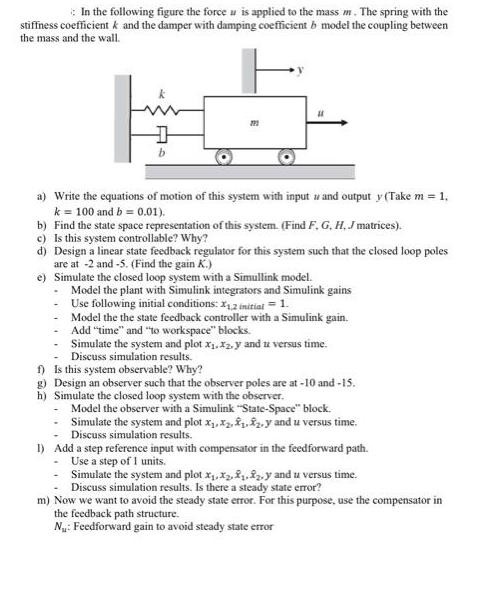
In the following figure the force u is applied to the mass m. The spring with the stiffness coefficient k and the damper with


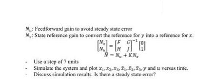
In the following figure the force u is applied to the mass m. The spring with the stiffness coefficient k and the damper with damping coefficient b model the coupling between the mass and the wall. k D 722 a) Write the equations of motion of this system with input w and output y (Take m = 1. k = 100 and b= 0.01). b) Find the state space representation of this system. (Find F, G, H, J matrices). c) Is this system controllable? Why? d) Design a linear state feedback regulator for this system such that the closed loop poles are at -2 and -5. (Find the gain K.) e) Simulate the closed loop system with a Simullink model. - Model the plant with Simulink integrators and Simulink gains Use following initial conditions: X2 initial = 1. Model the the state feedback controller with a Simulink gain. Add "time" and "to workspace" blocks. Simulate the system and plot x,x2, y and u versus time. Discuss simulation results. f) Is this system observable? Why? g) Design an observer such that the observer poles are at -10 and -15. h) Simulate the closed loop system with the observer. - Model the observer with a Simulink "State-Space" block. - Simulate the system and plot x....y and u versus time. Discuss simulation results. 1) Add a step reference input with compensator in the feedforward path. - Use a step of 1 units. - Simulate the system and plot x,x,..y and u versus time. Discuss simulation results. Is there a steady state error? m) Now we want to avoid the steady state error. For this purpose, use the compensator in the feedback path structure. N: Feedforward gain to avoid steady state error N: Feedforward gain to avoid steady state error Ny: State reference gain to convert the reference for y into a reference for x. M-E TO N = N +KN Use a step of 7 units Simulate the system and plot x.xz.x...3.y and u versus time. Discuss simulation results. Is there a steady state error?
Step by Step Solution
★★★★★
3.37 Rating (147 Votes )
There are 3 Steps involved in it
Step: 1
a The equations of motion for the given system can be written as follows m dxdt b dxdt k x F Where m mass of the system dxdt velocity of the mass dxdt acceleration of the mass b damping coefficient k ...
Get Instant Access to Expert-Tailored Solutions
See step-by-step solutions with expert insights and AI powered tools for academic success
Step: 2

Step: 3

Ace Your Homework with AI
Get the answers you need in no time with our AI-driven, step-by-step assistance
Get Started


