

Question: Write a c language code for this. GNG1106 Fundamentals of Engineering Computation Course Project Electrical Engineering Design of an RLC Electrical Circuit Electrical engineers often
Write a c language code for this.
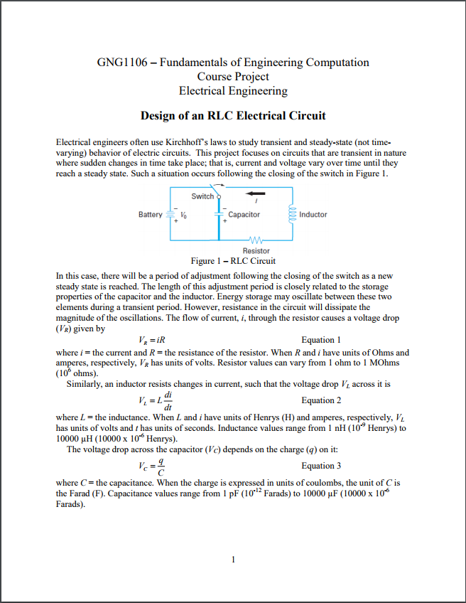
GNG1106 Fundamentals of Engineering Computation Course Project Electrical Engineering Design of an RLC Electrical Circuit Electrical engineers often use Kirchhoff's laws to study transient and steady-state (not time varying) behavior of electric circuits. This project focuses on circuits that are transient in nature where sudden changes in time take place; that is, current and voltage vary over time until they reach a steady state. Such a situation occurs following the closing of the switch in Figure 1 Switch Battery Inductor Resistor Figure 1 -RLC Circuit In this case, there will be a period of adjustment following the closing of the switch as a new steady state is reached. The length of this adjustment period is closely related to the storage properties of the capacitor and the inductor. Energy storage may oscillate between these two elements during a transient period. However, resistance in the circuit will dissipate the magnitude of the oscillations. The flow of current, i, through the resistor causes a voltage drop (VR) given by Equation 1 where i = the current and R = the resistance of the resistor. When R and i have units of Ohms and amperes, respectively, has units of volts. Resistor values can vary from 1 ohm to 1 MOhms (10 ohms). Similarly, an inductor resists changes in current, such that the voltage drop VL across it is Equation 2 dt where L-the inductance. When L and i have units of Henrys (H) and amperes, respectively, V has units of volts and t has units of seconds. Inductance values range from 1 nH (10Henrys) to 10000 HH (10000 x 10*6 Henrys). The voltage drop across the capacitor (Vc) depends on the charge (q) on it: Equation 3 where C= the capacitance. When the charge is expressed in units of coulombs, the unit of C is the Farad (F). Capacitance values range from 1 pF (10-12 Farads) to 10000 F (10000 x 10 Farads). GNG1106 Fundamentals of Engineering Computation Course Project Electrical Engineering Design of an RLC Electrical Circuit Electrical engineers often use Kirchhoff's laws to study transient and steady-state (not time varying) behavior of electric circuits. This project focuses on circuits that are transient in nature where sudden changes in time take place; that is, current and voltage vary over time until they reach a steady state. Such a situation occurs following the closing of the switch in Figure 1 Switch Battery Inductor Resistor Figure 1 -RLC Circuit In this case, there will be a period of adjustment following the closing of the switch as a new steady state is reached. The length of this adjustment period is closely related to the storage properties of the capacitor and the inductor. Energy storage may oscillate between these two elements during a transient period. However, resistance in the circuit will dissipate the magnitude of the oscillations. The flow of current, i, through the resistor causes a voltage drop (VR) given by Equation 1 where i = the current and R = the resistance of the resistor. When R and i have units of Ohms and amperes, respectively, has units of volts. Resistor values can vary from 1 ohm to 1 MOhms (10 ohms). Similarly, an inductor resists changes in current, such that the voltage drop VL across it is Equation 2 dt where L-the inductance. When L and i have units of Henrys (H) and amperes, respectively, V has units of volts and t has units of seconds. Inductance values range from 1 nH (10Henrys) to 10000 HH (10000 x 10*6 Henrys). The voltage drop across the capacitor (Vc) depends on the charge (q) on it: Equation 3 where C= the capacitance. When the charge is expressed in units of coulombs, the unit of C is the Farad (F). Capacitance values range from 1 pF (10-12 Farads) to 10000 F (10000 x 10 Farads)
Step by Step Solution
There are 3 Steps involved in it

Get step-by-step solutions from verified subject matter experts