

Question
(x_(1))/(b)ar (x_(2))/(b)ar (x_(3))x_(4)x_(5)(+)/(b)ar (x_(1))x_(3)x_(4)(+)/(b)ar (x_(1))x_(2)(x_(3))/(b)ar (x_(4))x_(5)(+)/(b)ar (x_(2))/(b)ar (x_(3))x_(4)x_(5) 80fF 2 Design Steps to be followed for design and characterization are described in the
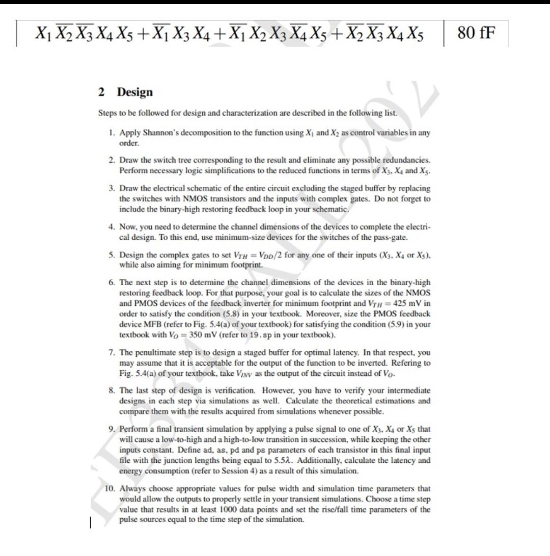
(x_(1))/(b)ar (x_(2))/(b)ar (x_(3))x_(4)x_(5)(+)/(b)ar (x_(1))x_(3)x_(4)(+)/(b)ar (x_(1))x_(2)(x_(3))/(b)ar (x_(4))x_(5)(+)/(b)ar (x_(2))/(b)ar (x_(3))x_(4)x_(5)\
80fF\ 2 Design\ Steps to be followed for design and characterization are described in the following list.\ Apply Shannon's decomposition to the function using
x_(1)and
x_(2)as control variables in any order.\ Draw the switch tree corresponding to the result and eliminate any possible redundancies. Perform necessary logic simplifications to the reduced functions in terms of
x_(3),x_(4)and
x_(5).\ Draw the electrical schematic of the entire circuit excluding the staged buffer by replacing the switches with NMOS transistors and the inputs with complex gates. Do not forget to include the binary-high restoring feedback loop in your schematic.\ Now, you need to determine the channel dimensions of the devices to complete the electrical design. To this end, use minimum-size devices for the switches of the pass-gate.\ Design the complex gates to set
V_(TH)=(V_(DD))/(2)for any one of their inputs or
{(
:x_(5))}, while also aiming for minimum footprint.\ The next step is to determine the channel dimensions of the devices in the binary-high restoring feedback loop. For that purpose, your goal is to calculate the sizes of the NMOS and PMOS devices of the feedback inverter for minimum footprint and
V_(TH)=425mVin order to satisfy the condition (5.8) in your textbook. Moreover, size the PMOS feedback device MFB (refer to Fig. 5.4(a) of your textbook) for satisfying the condition (5.9) in your textbook with
V_(O)=350mV(refer to
19.spin your textbook).\ The penultimate step is to design a staged buffer for optimal latency. In that respect, you may assume that it is acceptable for the output of the function to be inverted. Refering to Fig. 5.4(a) of your textbook, take
V_(INV)as the output of the circuit instead of
V_(O).\ The last step of design is verification. However, you have to verify your intermediate designs in each step via simulations as well. Calculate the theoretical estimations and compare them with the results acquired from simulations whenever possible.\ Perform a final transient simulation by applying a pulse signal to one of
x_(3),x_(4)or
x_(5)that will cause a low-to-high and a high-to-low transition in succession, while keeping the other inputs constant. Define ad, as, pd and ps parameters of each transistor in this final input energy consumption (refer to Session 4) as a result of this simulation.\ Always choose appropriate values for pulse width and simulation time parameters that would allow the outputs to properly settle in your transient simulations. Choose a time step value that results in at least 1000 data points and set the rise/fall time parameters of the pulse sources equal to the time step of the simulation.
Step by Step Solution
There are 3 Steps involved in it
Step: 1

Get Instant Access to Expert-Tailored Solutions
See step-by-step solutions with expert insights and AI powered tools for academic success
Step: 2

Step: 3
Ace Your Homework with AI
Get the answers you need in no time with our AI-driven, step-by-step assistance
Get Started
Database Marketing The Ultimate Marketing Tool
Authors: Edward L. Nash
1st Edition
0070460639, 978-0070460638