Answered step by step
Verified Expert Solution
Question
1 Approved Answer
You are tasked with the design of the three blades of a wind turbine to avoid excessive vibrations and prediction of critical wind speeds.
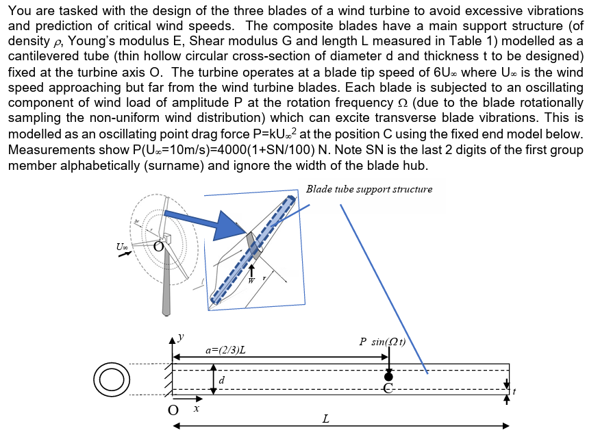
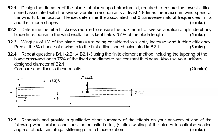
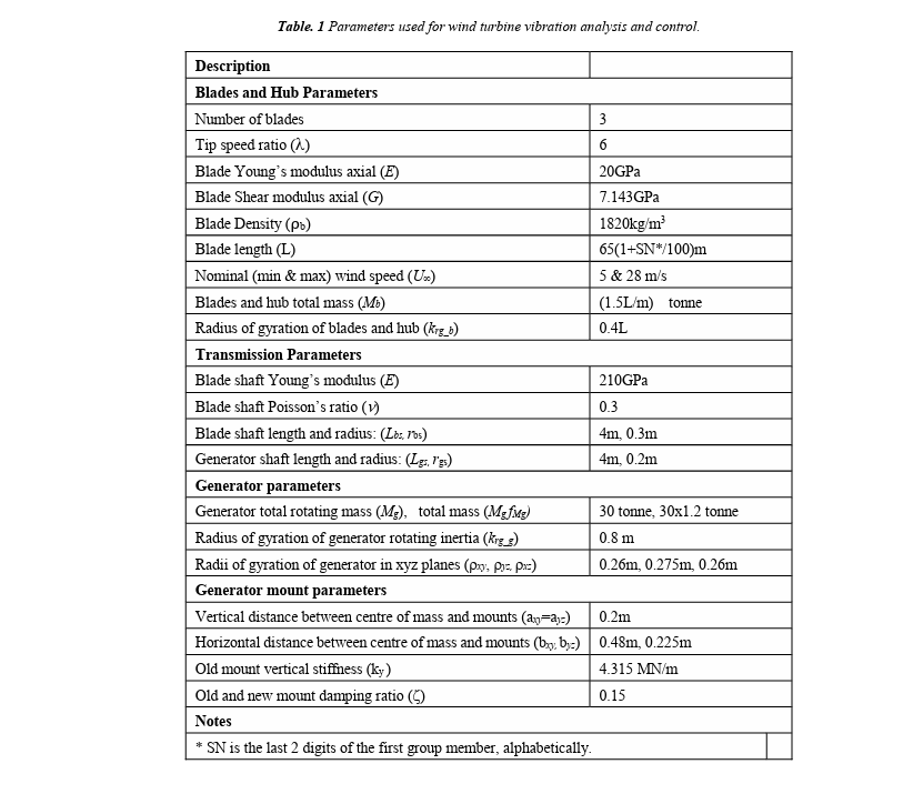
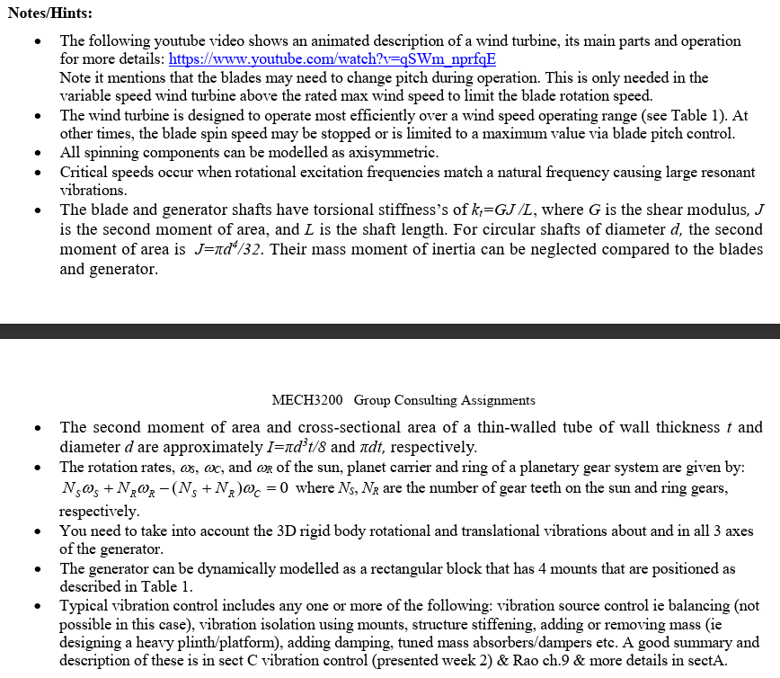
You are tasked with the design of the three blades of a wind turbine to avoid excessive vibrations and prediction of critical wind speeds. The composite blades have a main support structure (of density p, Young's modulus E, Shear modulus G and length L measured in Table 1) modelled as a cantilevered tube (thin hollow circular cross-section of diameter d and thickness t to be designed) fixed at the turbine axis O. The turbine operates at a blade tip speed of 6U- where U is the wind speed approaching but far from the wind turbine blades. Each blade is subjected to an oscillating component of wind load of amplitude P at the rotation frequency (due to the blade rotationally sampling the non-uniform wind distribution) which can excite transverse blade vibrations. This is modelled as an oscillating point drag force P=kU.. at the position C using the fixed end model below. Measurements show P(U=10m/s)=4000(1+SN/100) N. Note SN is the last 2 digits of the first group member alphabetically (surname) and ignore the width of the blade hub. Blade tube support structure Us Ox a=(2/3)L d L P sin(t) B2.1 Design the diameter of the blade tubular support structure, d, required to ensure the lowest critical speed associated with transverse vibration resonance is at least 1.8 times the maximum wind speed at the wind turbine location. Hence, determine the associated first 3 transverse natural frequencies in Hz and their mode shapes. (5 mks) B2.2 Determine the tube thickness required to ensure the maximum transverse vibration amplitude of any blade in response to the wind excitation is kept below 0.5% of the blade length. (5 mks) B2.3 Wingtips of 1% of the blade mass are being considered to slightly increase wind turbine efficiency. Predict the % change of a wingtip to the first critical speed calculated in B2.1. (5 mks) B2.4 Repeat questions B1.1-2,B1.4,B2.1-3 using the finite element method including the tapering of the blade cross-section to 75% of the fixed end diameter but constant thickness. Also use your uniform designed diameter of B2.1. Compare and discuss these results. (20 mks) d 0 x a = (2/3)L t L P sinnt C 0.75d B2.5 Research and provide a qualitative short summary of the effects on your answers of one of the following wind turbine conditions; aeroelastic flutter, (static) twisting of the blades to optimise section angle of attack, centrifugal stiffening due to blade rotation. (5 mks) Table. 1 Parameters used for wind turbine vibration analysis and control. Description Blades and Hub Parameters Number of blades Tip speed ratio (2) Blade Young's modulus axial (E) Blade Shear modulus axial (G) Blade Density (pb) Blade length (L) Nominal (min & max) wind speed (Un) Blades and hub total mass (Mb) Radius of gyration of blades and hub (krg b) Transmission Parameters Blade shaft Young's modulus (E) Blade shaft Poisson's ratio () Blade shaft length and radius: (Lbs, Pos) Generator shaft length and radius: (Lgs, Igs) Generator parameters Generator total rotating mass (Mg), total mass (MgfMg) Radius of gyration of generator rotating inertia (krg_g) Radii of gyration of generator in xyz planes (py, pz. px=) Generator mount parameters Vertical distance between centre of mass and mounts (a-a-) Horizontal distance between centre of mass and mounts (by by) Old mount vertical stiffness (ky) Old and new mount damping ratio ( Notes * SN is the last 2 digits of the first group member, alphabetically. 3 6 20GPa 7.143GPa 1820kg/m 65(1+SN*/100)m 5 & 28 m/s (1.5L/m) tonne 0.4L 210GPa 0.3 4m, 0.3m 4m, 0.2m 30 tonne, 30x1.2 tonne 0.8 m 0.26m, 0.275m, 0.26m 0.2m 0.48m, 0.225m 4.315 MN/m 0.15 Notes/Hints: The following youtube video shows an animated description of a wind turbine, its main parts and operation for more details: https://www.youtube.com/watch?v=qSWm_nprfqE Note it mentions that the blades may need to change pitch during operation. This is only needed in the variable speed wind turbine above the rated max wind speed to limit the blade rotation speed. The wind turbine is designed to operate most efficiently over a wind speed operating range (see Table 1). At other times, the blade spin speed may be stopped or is limited to a maximum value via blade pitch control. All spinning components can be modelled as axisymmetric. Critical speeds occur when rotational excitation frequencies match a natural frequency causing large resonant vibrations. The blade and generator shafts have torsional stiffness's of k=GJ /L, where G is the shear modulus, J is the second moment of area, and I is the shaft length. For circular shafts of diameter d, the second moment of area is J=d/32. Their mass moment of inertia can be neglected compared to the blades and generator. MECH3200 Group Consulting Assignments The second moment of area and cross-sectional area of a thin-walled tube of wall thickness and diameter d are approximately I=dt/8 and dt, respectively. The rotation rates, cs, ac, and or of the sun, planet carrier and ring of a planetary gear system are given by: Nsos + NRWR-(Ng + N)@c=0 where Ns, NR are the number of gear teeth on the sun and ring gears, respectively. You need to take into account the 3D rigid body rotational and translational vibrations about and in all 3 axes of the generator. The generator can be dynamically modelled as a rectangular block that has 4 mounts that are positioned as described in Table 1. Typical vibration control includes any one or more of the following: vibration source control ie balancing (not possible in this case), vibration isolation using mounts, structure stiffening, adding or removing mass (ie designing a heavy plinth/platform), adding damping, tuned mass absorbers/dampers etc. A good summary and description of these is in sect C vibration control (presented week 2) & Rao ch.9 & more details in sectA.
Step by Step Solution
There are 3 Steps involved in it
Step: 1

Get Instant Access to Expert-Tailored Solutions
See step-by-step solutions with expert insights and AI powered tools for academic success
Step: 2

Step: 3

Ace Your Homework with AI
Get the answers you need in no time with our AI-driven, step-by-step assistance
Get Started


