Answered step by step
Verified Expert Solution
Question
1 Approved Answer
You are working in a water engineering consulting company as a graduate civil engineer. Your company has just won a contract from Torrents River
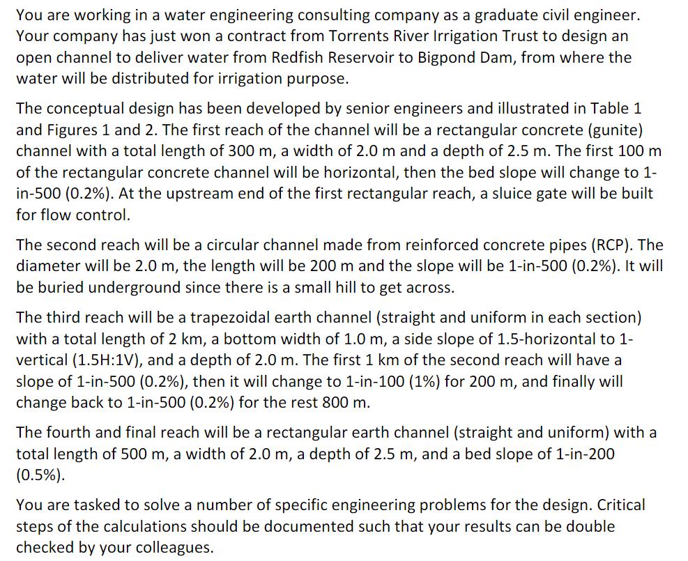
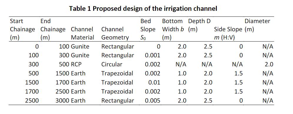
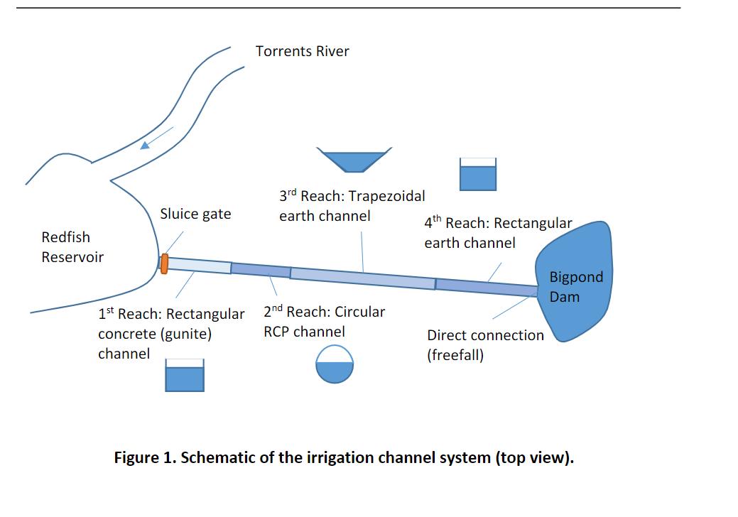
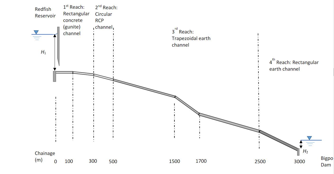
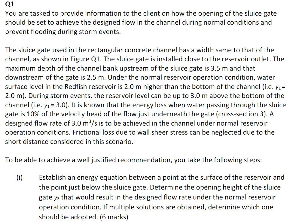
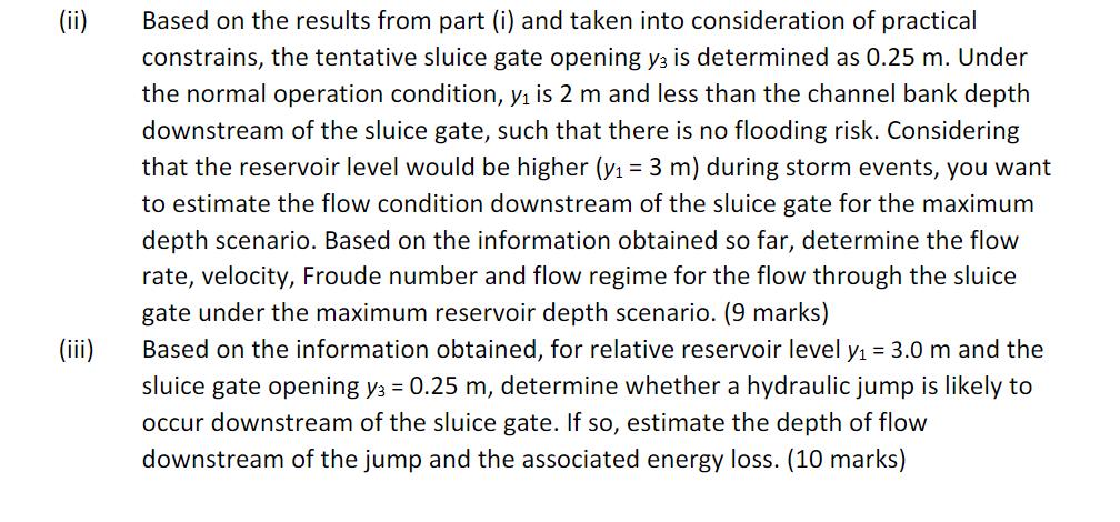
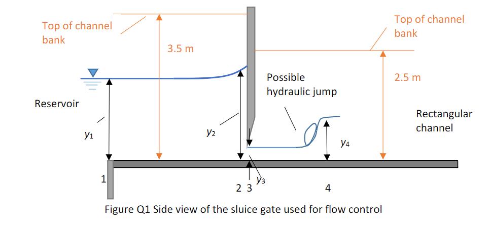
You are working in a water engineering consulting company as a graduate civil engineer. Your company has just won a contract from Torrents River Irrigation Trust to design an open channel to deliver water from Redfish Reservoir to Bigpond Dam, from where the water will be distributed for irrigation purpose. The conceptual design has been developed by senior engineers and illustrated in Table 1 and Figures 1 and 2. The first reach of the channel will be a rectangular concrete (gunite) channel with a total length of 300 m, a width of 2.0 m and a depth of 2.5 m. The first 100 m of the rectangular concrete channel will be horizontal, then the bed slope will change to 1- in-500 (0.2%). At the upstream end of the first rectangular reach, a sluice gate will be built for flow control. The second reach will be a circular channel made from reinforced concrete pipes (RCP). The diameter will be 2.0 m, the length will be 200 m and the slope will be 1-in-500 (0.2%). It will be buried underground since there is a small hill to get across. The third reach will be a trapezoidal earth channel (straight and uniform in each section) with a total length of 2 km, a bottom width of 1.0 m, a side slope of 1.5-horizontal to 1- vertical (1.5H:1V), and a depth of 2.0 m. The first 1 km of the second reach will have a slope of 1-in-500 (0.2%), then it will change to 1-in-100 (1%) for 200 m, and finally will change back to 1-in-500 (0.2%) for the rest 800 m. The fourth and final reach will be a rectangular earth channel (straight and uniform) with a total length of 500 m, a width of 2.0 m, a depth of 2.5 m, and a bed slope of 1-in-200 (0.5%). You are tasked to solve a number of specific engineering problems for the design. Critical steps of the calculations should be documented such that your results can be double checked by your colleagues. Table 1 Proposed design of the irrigation channel Bed Bottom Depth D Slope Width b (m) So (m) Start End Chainage Chainage Channel (m) (m) Material 0 100 300 500 1500 1700 2500 100 Gunite 300 Gunite 500 RCP 1500 Earth 1700 Earth 2500 Earth 3000 Earth Channel Geometry Rectangular 0 Rectangular 0.001 Circular 0.002 Trapezoidal 0.002 Trapezoidal 0.01 Trapezoidal 0.002 Rectangular 0.005 2.0 2.5 2.0 2.5 N/A N/A 1.0 2.0 1.0 2.0 1.0 2.0 2.0 2.5 Diameter Side Slope (m) m (H:V) 0 0 N/A 1.5 1.5 1.5 0 N/A N/A 2.0 N/A N/A N/A N/A Redfish Reservoir Sluice gate 1st Reach: Rectangular concrete (gunite) channel Torrents River 3rd Reach: Trapezoidal earth channel 2nd Reach: Circular RCP channel 4th Reach: Rectangular earth channel Direct connection (freefall) Bigpond Dam Figure 1. Schematic of the irrigation channel system (top view). Redfish Reservoir H1 Chainage (m) 0 1st Reach: Rectangular concrete (gunite) channel. 100 2nd Reach: Circular RCP channel, 300 500 rd 3 Reach: Trapezoidal earth channel 1500 1700 2500 th 4 Reach: Rectangular earth channel H 3000 Bigpo Dam Q1 You are tasked to provide information to the client on how the opening of the sluice gate should be set to achieve the designed flow in the channel during normal conditions and prevent flooding during storm events. The sluice gate used in the rectangular concrete channel has a width same to that of the channel, as shown in Figure Q1. The sluice gate is installed close to the reservoir outlet. The maximum depth of the channel bank upstream of the sluice gate is 3.5 m and that downstream of the gate is 2.5 m. Under the normal reservoir operation condition, water surface level in the Redfish reservoir is 2.0 m higher than the bottom of the channel (i.e. y= 2.0 m). During storm events, the reservoir level can be up to 3.0 m above the bottom of the channel (i.e. y= 3.0). It is known that the energy loss when water passing through the sluice gate is 10% of the velocity head of the flow just underneath the gate (cross-section 3). A designed flow rate of 3.0 m/s is to be achieved in the channel under normal reservoir operation conditions. Frictional loss due to wall sheer stress can be neglected due to the short distance considered in this scenario. To be able to achieve a well justified recommendation, you take the following steps: (i) Establish an energy equation between a point at the surface of the reservoir and the point just below the sluice gate. Determine the opening height of the sluice gate y3 that would result in the designed flow rate under the normal reservoir operation condition. If multiple solutions are obtained, determine which one should be adopted. (6 marks) (iii) Based on the results from part (i) and taken into consideration of practical constrains, the tentative sluice gate opening y3 is determined as 0.25 m. Under the normal operation condition, y is 2 m and less than the channel bank depth downstream of the sluice gate, such that there is no flooding risk. Considering that the reservoir level would be higher (y = 3 m) during storm events, you want to estimate the flow condition downstream of the sluice gate for the maximum depth scenario. Based on the information obtained so far, determine the flow rate, velocity, Froude number and flow regime for the flow through the sluice gate under the maximum reservoir depth scenario. (9 marks) Based on the information obtained, for relative reservoir level y = 3.0 m and the sluice gate opening y3 = 0.25 m, determine whether a hydraulic jump is likely to occur downstream of the sluice gate. If so, estimate the depth of flow downstream of the jump and the associated energy loss. (10 marks) Top of channel bank Reservoir Y 1 3.5 m Y2 Possible hydraulic jump Y4 23 4 Figure Q1 Side view of the sluice gate used for flow control Top of channel bank 2.5 m Rectangular channel
Step by Step Solution
★★★★★
3.42 Rating (165 Votes )
There are 3 Steps involved in it
Step: 1

Get Instant Access to Expert-Tailored Solutions
See step-by-step solutions with expert insights and AI powered tools for academic success
Step: 2

Step: 3

Ace Your Homework with AI
Get the answers you need in no time with our AI-driven, step-by-step assistance
Get Started


