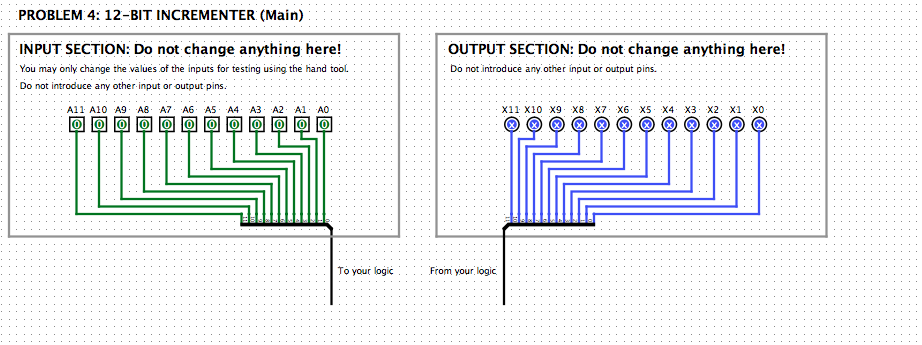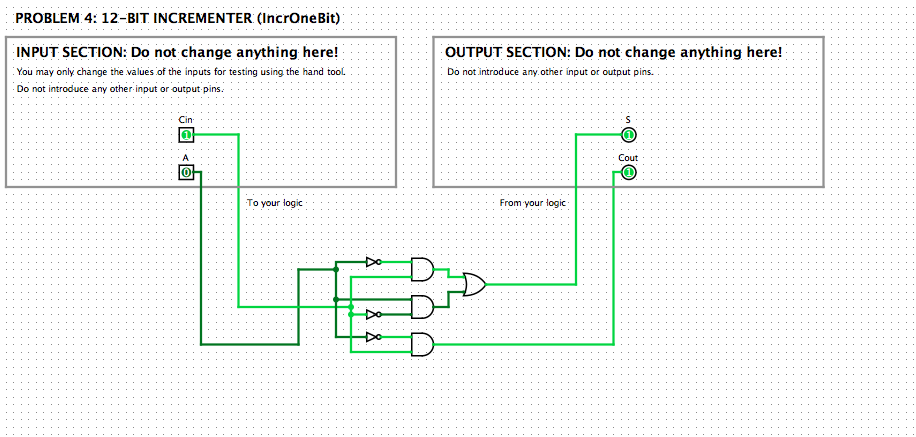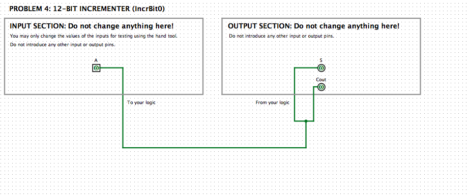


You will design a circuit that takes a 12-bit 2's complement number A as input, and produces A1. You need to do a stepwise design. 1. First understand the algorithm that your circuit is to implement. To add 1 to any (2's complement or unsigned) binary integer, we use the grade school algorithm: work our way from the least significant bit (LSB) to the left towards the most significant bit (MSB). Work out three examples on paper 2. Decompose the algorithm into a set of functions for each bit and write their truth tables. The input at any bit position is an input bit A and a carry bit Cin, and the result of the addition at that position is an output bit S, and a carry bit Cout. So, our first step is to write a truth table that specifies these two outputs as a function of the two inputs. Since there are two inputs and two outputs, your truth table should have 4 rows and 4 columns. 3. Now implement and test it in Logisim First, build the P4_IncrOneBit sub-circuit that deals with a single bit position as explained above. In the P4 Main sub-circuit, build your logic by making 12 copies of the P4 incr neBit sub Circuit and connecting ema propriate The input to our circuit should me om splitter in the input section. The output of your circuit should go to the splitter in the output section. Don't add any additional input or output pins in the main circuit. If you need a constant 0 or 1, use the Constant element under the Wiring library. Finally, note that the bit-0 sub-circuit can be simplified so that it doesn't need a Cin input. Build the P4_IncrBito sub-circuit and use that in the P4_Main sub-circuit for the LSB instead of P4 IncrOneBit. You will design a circuit that takes a 12-bit 2's complement number A as input, and produces A1. You need to do a stepwise design. 1. First understand the algorithm that your circuit is to implement. To add 1 to any (2's complement or unsigned) binary integer, we use the grade school algorithm: work our way from the least significant bit (LSB) to the left towards the most significant bit (MSB). Work out three examples on paper 2. Decompose the algorithm into a set of functions for each bit and write their truth tables. The input at any bit position is an input bit A and a carry bit Cin, and the result of the addition at that position is an output bit S, and a carry bit Cout. So, our first step is to write a truth table that specifies these two outputs as a function of the two inputs. Since there are two inputs and two outputs, your truth table should have 4 rows and 4 columns. 3. Now implement and test it in Logisim First, build the P4_IncrOneBit sub-circuit that deals with a single bit position as explained above. In the P4 Main sub-circuit, build your logic by making 12 copies of the P4 incr neBit sub Circuit and connecting ema propriate The input to our circuit should me om splitter in the input section. The output of your circuit should go to the splitter in the output section. Don't add any additional input or output pins in the main circuit. If you need a constant 0 or 1, use the Constant element under the Wiring library. Finally, note that the bit-0 sub-circuit can be simplified so that it doesn't need a Cin input. Build the P4_IncrBito sub-circuit and use that in the P4_Main sub-circuit for the LSB instead of P4 IncrOneBit


