

Question
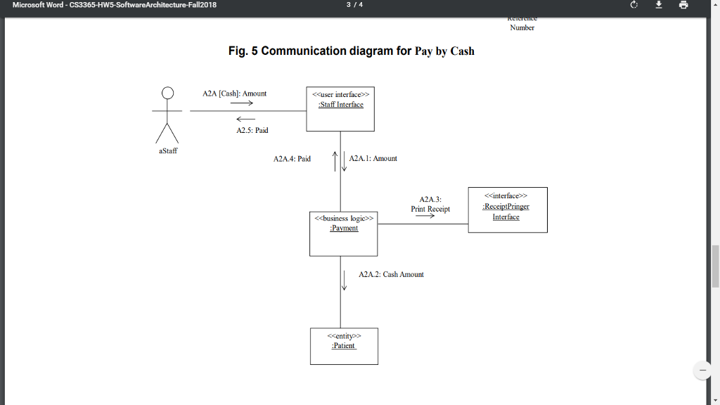
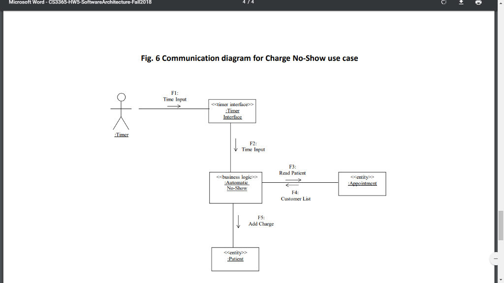
Your are required to develop the software architecture for a healthcare system, which provides check-in, payment, and automatic no-show charge use cases depicted in Figs.
Your are required to develop the software architecture for a healthcare system, which provides check-in, payment, and automatic no-show charge use cases depicted in Figs. 1-6 using the communication diagram. Develop the software architecture for a healthcare system in the following order:
1. Develop the consolidated communication diagram that merges all communication diagrams to show all objects and their interaction. (3 pts)
2. Determine the subsystems (or components) of healthcare system and depict them on the consolidated communication diagram. (3 pts)
3. Depict function call or message communication for interactions between objects or between subsystems on the consolidated communication diagram. (3 pts)
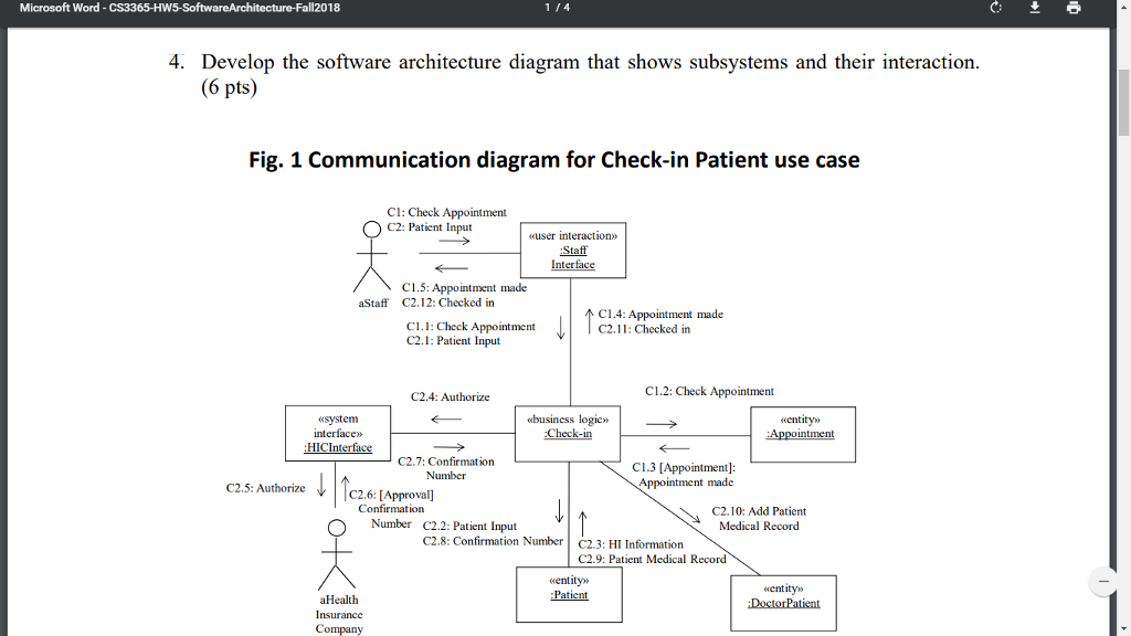
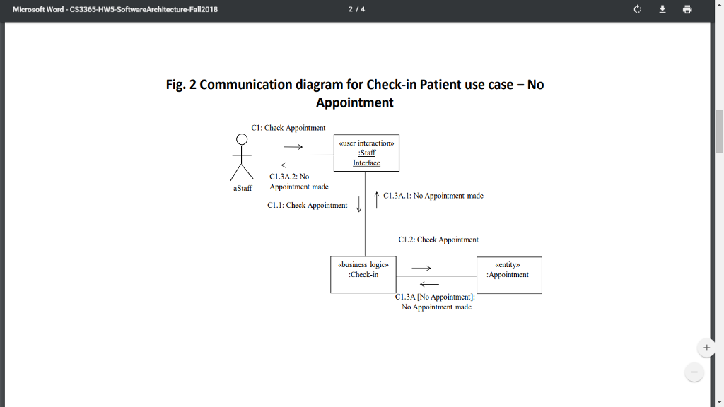
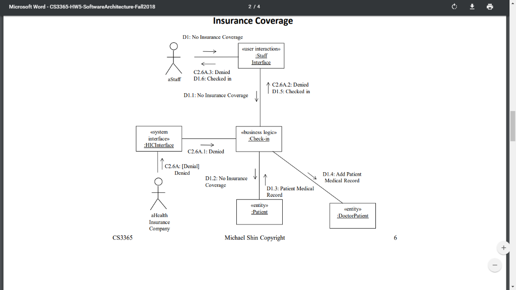
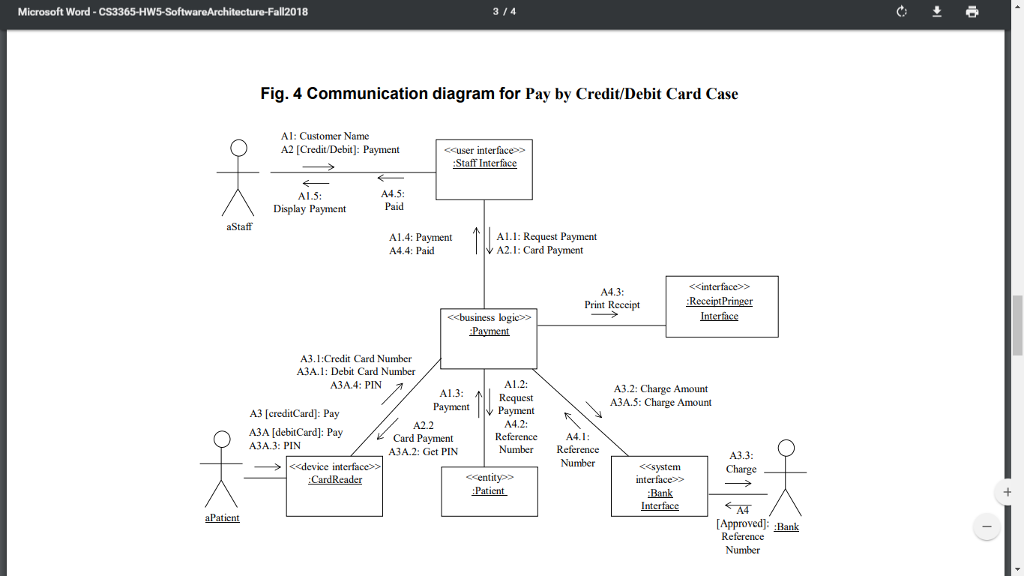
4. Develop the software architecture diagram that shows subsystems and their interaction. (6 pts)
Step by Step Solution
There are 3 Steps involved in it
Step: 1

Get Instant Access to Expert-Tailored Solutions
See step-by-step solutions with expert insights and AI powered tools for academic success
Step: 2

Step: 3
Ace Your Homework with AI
Get the answers you need in no time with our AI-driven, step-by-step assistance
Get Started
Pro PowerShell For Database Developers
Authors: Bryan P Cafferky
1st Edition
1484205413, 9781484205419