

Question
%----- YOUR CODE GOES BELOW HERE ----- function wheelVel = vw2wheels(vw) % Inputs: % vw is the velocity vector (v, omega) in units of metres/s
%----- YOUR CODE GOES BELOW HERE -----
function wheelVel = vw2wheels(vw)
% Inputs:
% vw is the velocity vector (v, omega) in units of metres/s and radians/s
% Return:
% wheelVel is the wheel velocity vector (vleft, vright) each in the range -100 to +100 to achieve
% this velocity
end
function vw = wheels2vw(wheelVel)
% Inputs:
% wheelVel is the wheel velocity vector (vleft, vright) each in the range -100 to +100
% Return:
% vw is the resulting velocity vector (v, omega) in units of metres/s and radians/s
end
function qd = qdot(q, vel)
% Inputs:
% q is the configuration vector (x, y, theta) in units of metres and radians
% vel is the velocity vector (vleft, vright) each in the range -100 to +100
% Return:
% qd is the vector (xdot, ydot, thetadot) in units of metres/s and radians/s
end
function qnew = qupdate(q, vel, dt)
% Inputs:
% q is the configuration vector (x, y, theta) in units of metres and radians
% vel is the velocity vector (vleft, vright) each in the range -100 to +100
% dt is the length of the integration timestep in units of seconds
% Return:
% qnew is the new configuration vector vector (x, y, theta) in units of metres and radians at the
% end of the time interval.
end
function vel = control(q, point)
% Inputs:
% q is the initial configuration vector (x, y, theta) in units of metres and radians
% point is the vector (x, y) specifying the goal point of the robot
end
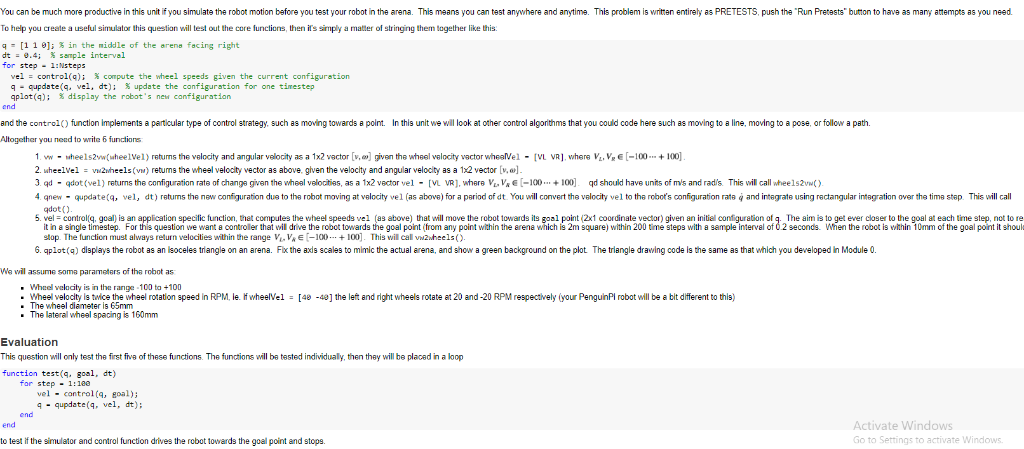
You can be much more productive in this unit if you simulate the robot motion before you test your robot in the arena. This means you can test anywhere and anytime. This problem is writen entirely as PRETESTS, push the "Run Pretests button to have as many atempts as you need. To help you create a useful simulator this question will test out the core functions, then it's simply a matter of stringing them tagether like this q [1 1 9], % in the middle of the arena facing right dt -9.4; sample interval for step 1:Nsteps vel : control(q); compute the wheel speeds given the current configuration q-qupdate(q, vel, dt); % update the configuration for one timestep aplot(9); % display the robot's new configuration end and the control) function implements a particular type of control strategy, such as moving towards a point. In this unit we will look at other control algonthms that you could code here such as moving to a line, moving to a pose, or follow a path Atogether you need to write 6 functions 1. v " " heels2 wheelvel) retums the velocity and angular velocity as a 1x2 vector a given the heel volocity v ctor hear el " VL VR where VL,VE 100 + 100 2. wheelVelv2hls(vw) retums the wheel velocity vector as above, glven the velocity and angular velocity as a 12 vector [v, 3 ad - qdot (vel) returns the configuration rats of changa given the wheal velocitias, as a 1x2 vector vel - [VL VR, where VV-100100 qd should have units of m's and radis. This will call whee1s2vwt) 4 qnew- qupdate(q, vel, dt) retums the new configuration dua to tha robot moving at velocity vel (as above) for a period of dt. You will convert the velocity vel to the robot's configuration rate and integrate using ractangular intagration ovar the tima stap. This will call qdot() 5. vel-control(q, goal) is an application specilic function, that computes the wheel speeds vel (as above) that will move the robot towards its goal point (2x1 coordinate vector) given an initial configuration of q. The aim is to get ever closer to the goal at each time step, not to re it in a single timestep. For this question we want a controller that will drive the robet towards the goal point (trom any point within the arena which is 2m square) within 200 time steps with a sample interval of 02 seconds. When the robot is within 10mm of the goal point it shoul stop. The function must always return velocities within the range Vi. V E-100100]. This will call vwzwheels(). 6. qplot(q) displays the robot as an lsoceles triangla on an arena. Flx the axis scales to mimic the actual arena, and show a green background on the plot The triangle drawing code is the same as that which you developed in Module 0. We wil assume soma parameters of the robot as s in the range-100 ta +100 - Wheel velocity is twice the wheel rotation speed in RPM le. wheelVel - [48 -4] the left and right wheels rotae t 20 and-20 RPM respectively (your PenguinPl robot will be a bit different to this) The wheel diameter is 65mm The laterall wheel spacing is 160mm Evaluation This question will only test the first fivs of these functions. The functions will ba tested individualy, then thay will be placed in a loop function test(q, goal. dt) for step - 1:180 vel - control(q, goal) 4 -qupdate(4, vel, dt); end end ivate Windows to test if the simulator and control function drives the robot towards the goal point and stops. Go to Settings to activate Windows You can be much more productive in this unit if you simulate the robot motion before you test your robot in the arena. This means you can test anywhere and anytime. This problem is writen entirely as PRETESTS, push the "Run Pretests button to have as many atempts as you need. To help you create a useful simulator this question will test out the core functions, then it's simply a matter of stringing them tagether like this q [1 1 9], % in the middle of the arena facing right dt -9.4; sample interval for step 1:Nsteps vel : control(q); compute the wheel speeds given the current configuration q-qupdate(q, vel, dt); % update the configuration for one timestep aplot(9); % display the robot's new configuration end and the control) function implements a particular type of control strategy, such as moving towards a point. In this unit we will look at other control algonthms that you could code here such as moving to a line, moving to a pose, or follow a path Atogether you need to write 6 functions 1. v " " heels2 wheelvel) retums the velocity and angular velocity as a 1x2 vector a given the heel volocity v ctor hear el " VL VR where VL,VE 100 + 100 2. wheelVelv2hls(vw) retums the wheel velocity vector as above, glven the velocity and angular velocity as a 12 vector [v, 3 ad - qdot (vel) returns the configuration rats of changa given the wheal velocitias, as a 1x2 vector vel - [VL VR, where VV-100100 qd should have units of m's and radis. This will call whee1s2vwt) 4 qnew- qupdate(q, vel, dt) retums the new configuration dua to tha robot moving at velocity vel (as above) for a period of dt. You will convert the velocity vel to the robot's configuration rate and integrate using ractangular intagration ovar the tima stap. This will call qdot() 5. vel-control(q, goal) is an application specilic function, that computes the wheel speeds vel (as above) that will move the robot towards its goal point (2x1 coordinate vector) given an initial configuration of q. The aim is to get ever closer to the goal at each time step, not to re it in a single timestep. For this question we want a controller that will drive the robet towards the goal point (trom any point within the arena which is 2m square) within 200 time steps with a sample interval of 02 seconds. When the robot is within 10mm of the goal point it shoul stop. The function must always return velocities within the range Vi. V E-100100]. This will call vwzwheels(). 6. qplot(q) displays the robot as an lsoceles triangla on an arena. Flx the axis scales to mimic the actual arena, and show a green background on the plot The triangle drawing code is the same as that which you developed in Module 0. We wil assume soma parameters of the robot as s in the range-100 ta +100 - Wheel velocity is twice the wheel rotation speed in RPM le. wheelVel - [48 -4] the left and right wheels rotae t 20 and-20 RPM respectively (your PenguinPl robot will be a bit different to this) The wheel diameter is 65mm The laterall wheel spacing is 160mm Evaluation This question will only test the first fivs of these functions. The functions will ba tested individualy, then thay will be placed in a loop function test(q, goal. dt) for step - 1:180 vel - control(q, goal) 4 -qupdate(4, vel, dt); end end ivate Windows to test if the simulator and control function drives the robot towards the goal point and stops. Go to Settings to activate WindowsStep by Step Solution
There are 3 Steps involved in it
Step: 1

Get Instant Access to Expert-Tailored Solutions
See step-by-step solutions with expert insights and AI powered tools for academic success
Step: 2

Step: 3
Ace Your Homework with AI
Get the answers you need in no time with our AI-driven, step-by-step assistance
Get Started
Machine Learning And Knowledge Discovery In Databases European Conference Ecml Pkdd 2018 Dublin Ireland September 10 14 2018 Proceedings Part 1 Lnai 11051
Authors: Michele Berlingerio ,Francesco Bonchi ,Thomas Gartner ,Neil Hurley ,Georgiana Ifrim
1st Edition
3030109240, 978-3030109240