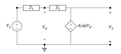
In the circuit of Fig. 12-72, Z 1 = R + 1/(Cs) and Z 2 = R,
Question:
In the circuit of Fig. 12-72, Z1 = R + 1/(Cs) and Z2 = R, with RC = 0.5 ms and A = ∞ (an ideal op amp).
(a) Find the frequency response H (jω) =V2/V1 .
(b) Determine the order and type of the filter.
(c) Specify asymptotic responses at low and high frequencies and determine the 3-dB attenuation frequency f1 in Hz.
(d) Plot the Bode diagram.

Step by Step Answer:
Related Book For 

Schaum S Outline Of Electric Circuits
ISBN: 9781260011968
7th Edition
Authors: Mahmood Nahvi, Joseph Edminister
Question Posted:


