

Question: (a) Design a four-resistor bias network with the configuration shown in Figure P5.61 to yield (Q)-point values of (I_{C Q}=0.50 mathrm{~mA}) and (V_{C E Q}=2.5
(a) Design a four-resistor bias network with the configuration shown in Figure P5.61 to yield \(Q\)-point values of \(I_{C Q}=0.50 \mathrm{~mA}\) and \(V_{C E Q}=2.5 \mathrm{~V}\). The bias voltages are \(V^{+}=3 \mathrm{~V}\) and \(V^{-}=-3 \mathrm{~V}\). The transistor current gain is \(\beta=120\). The voltage across the emitter resistor should be approximately 0.7V.
(b) Replace the designed resistors in part (a) with standard resistors with values closest to the designed values. Determine the resulting \(Q\)-point.
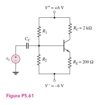
+1 V+ = +6 V R Rc = 2 k www Cc HH R RE=200 2 Figure P5.61 V-=-6 V
Step by Step Solution
3.43 Rating (153 Votes )
There are 3 Steps involved in it

Get step-by-step solutions from verified subject matter experts