

Question: (a) Design a four-resistor bias network with the configuration shown in Figure P5.77 such that the (Q)-point values are (I_{C Q}=1.2 mathrm{~mA}) and (V_{E C
(a) Design a four-resistor bias network with the configuration shown in Figure P5.77 such that the \(Q\)-point values are \(I_{C Q}=1.2 \mathrm{~mA}\) and \(V_{E C Q}=6 \mathrm{~V}\). The bias voltages are \(V^{+}=9 \mathrm{~V}\) and \(V^{-}=-9 \mathrm{~V}\). A transistor with \(\beta=75\) is available. The voltage across the emitter resistor should be approximately 1.5V.
(b) Replace the designed resistors in part (a) with standard resistors with values closest to the designed values. Determine the resulting \(Q\)-point.
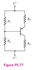
R RE R RC V- Figure P5.77
Step by Step Solution
There are 3 Steps involved in it
1 Expert Approved Answer
Step: 1 Unlock

Question Has Been Solved by an Expert!
Get step-by-step solutions from verified subject matter experts
Step: 2 Unlock
Step: 3 Unlock