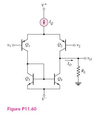
Reconsider the circuit in Figure P11.60 except that (1 mathrm{k} Omega) resistors are inserted at the emitters
Question:
Reconsider the circuit in Figure P11.60 except that \(1 \mathrm{k} \Omega\) resistors are inserted at the emitters of the active load transistors \(Q_{3}\) and \(Q_{4}\) as in the circuit in Figure P11.66. Assume the same transistor parameters as in Problem 11.60.
(a) Determine the output resistance looking into the output of the diff-amp circuit.
(b) Find the open-circuit differential-mode voltage gain.

Fantastic news! We've Found the answer you've been seeking!
Step by Step Answer:
Related Book For 

Microelectronics Circuit Analysis And Design
ISBN: 9780071289474
4th Edition
Authors: Donald A. Neamen
Question Posted:


