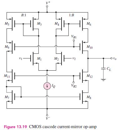
Redesign the CMOS cascode current mirror in Figure 13.19 to provide a differential voltage gain of 20,000.
Question:
Redesign the CMOS cascode current mirror in Figure 13.19 to provide a differential voltage gain of 20,000. The bias current and transistor parameters are the same as in Problem 13.46.
(a) Design the basic amplifier to provide the specified voltage gain.
(b) Design a current source to provide the necessary bias current.
(c) Determine the unity gain bandwidth if the capacitance at the output terminal is \(3 \mathrm{pF}\).
Data From Problem 13.46:-
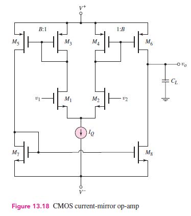
The CMOS current gain op-amp in Figure 13.18 is to be redesigned to provide a differential voltage gain of 400 . The transistor parameters are \(V_{T N}=0.5 \mathrm{~V}, V_{T P}=-0.5 \mathrm{~V}, k_{n}^{\prime}=80 \mu \mathrm{A} / \mathrm{V}^{2}, k_{p}^{\prime}=35 \mu \mathrm{A} / \mathrm{V}^{2}, \lambda_{n}=\) \(0.015 \mathrm{~V}^{-1}\), and \(\lambda_{p}=0.02 \mathrm{~V}^{-1}\). The bias current is to be \(I_{Q}=80 \mu \mathrm{A}\). Let \(B=2.5\).
(a) Design the basic amplifier to provide the specified voltage gain.
(b) Design a current source to provide the necessary bias current.
(c) Determine the unity-gain bandwidth if the capacitance at the output terminal is \(3 \mathrm{pF}\).


Step by Step Answer:

Microelectronics Circuit Analysis And Design
ISBN: 9780071289474
4th Edition
Authors: Donald A. Neamen


