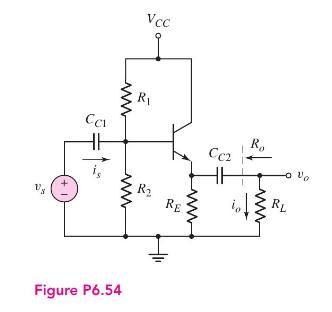
The output of an amplifier can be represented by (v_{s}=4 sin omega t(mathrm{~V})) and (R_{S}=4 mathrm{k} Omega).
Question:
The output of an amplifier can be represented by \(v_{s}=4 \sin \omega t(\mathrm{~V})\) and \(R_{S}=4 \mathrm{k} \Omega\). An emitter-follower circuit, with the configuration shown in Figure 6.54, is to be designed such that the output signal does not vary by more than 5 percent when a load in the range \(R_{L}=4\) to \(10 \mathrm{k} \Omega\) is connected to the output. The transistor current gain is in the range \(90 \leq \beta \leq 130\) and the Early voltage is \(V_{A}=\infty\). For your design, find the minimum and maximum possible value of the output voltage.

Fantastic news! We've Found the answer you've been seeking!
Step by Step Answer:
Related Book For 

Microelectronics Circuit Analysis And Design
ISBN: 9780071289474
4th Edition
Authors: Donald A. Neamen
Question Posted:


