(a) Find the driving point impedance seen by the voltage source in Figure P11-3 and the voltage...
Question:
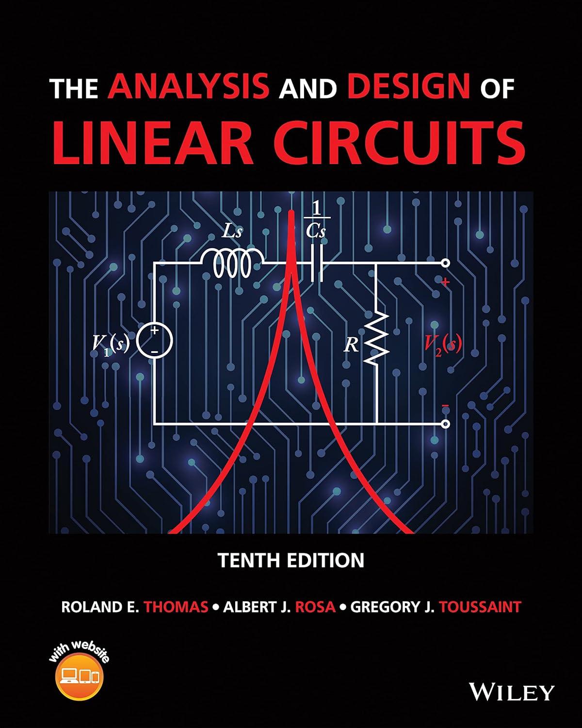
(a) Find the driving point impedance seen by the voltage source in Figure P11-3 and the voltage transfer function \(T_{\mathbf{V}}(s)=V_{\mathbf{2}}(s) / V_{1}(s)\).
(b) Select values of \(R, L\), and \(C\) so that the transfer function has a pair of real poles at \(s=-10000 \mathrm{rad} / \mathrm{s}\). Where are the zeros under these conditions?
(c) Use Multisim to plot the frequency response of your circuit. Plot your graph in dB from \(1 \mathrm{~Hz}\) to \(1 \mathrm{MHz}\). What type of filter is your device?
Fantastic news! We've Found the answer you've been seeking!
Step by Step Answer:
Related Book For 

The Analysis And Design Of Linear Circuits
ISBN: 9781119913023
10th Edition
Authors: Roland E. Thomas, Albert J. Rosa, Gregory J. Toussaint
Question Posted:


