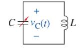
In Section 6-1, Figure 6-2 (g) shows an air-tunable capacitor as one example of the capacitor types.
Question:
In Section 6-1, Figure 6-2 (g) shows an air-tunable capacitor as one example of the capacitor types. This type of device can vary its capacitance similar to how a potentiometer can vary its resistance. Changing the capacitance in a circuit can change the frequency at which it operates. This device was common in early radio sets. Today, semiconductor devices perform a similar function. Suppose we are given the circuit in Figure P6-55 with a capacitor connected in parallel with an inductor. There are no other devices in the circuit. The capacitor has an initial voltage \(v\) \({ }_{\mathrm{C}}(\mathrm{o})=V_{\mathrm{o}} \mathrm{V}\), and the inductor's initial current is \(i_{\mathrm{L}}(\mathrm{O})=\mathrm{O} \mathrm{A}\).

The differential equation for the voltage across the capacitor in this circuit is given by
\[
\frac{d^{2} v_{\mathrm{C}}(t)}{d t^{2}}+\frac{1}{L C} v_{\mathrm{C}}(t)=0
\]
We will learn more about solving this type of differential equation in the next chapter and beyond. The solution to this differential equation is
\[
v_{\mathrm{C}}(t)=V_{0} \cos \left(\frac{t}{\sqrt{L C}}ight), t \geq 0
\]
Using MATLAB, plot on a semi-log scale (logarithmic on the horizontal and linear on the vertical) the radian frequency of \(v_{\mathrm{C}}\) ( \(t\) ) versus the capacitance of the circuit. Then using \(L=1 \mathrm{mH}\), design a tank circuit (what they call an \(L C\) circuit in the radio business), so to be able to receive a radio station at \(850 \mathrm{kHz}\).
Step by Step Answer:

The Analysis And Design Of Linear Circuits
ISBN: 9781119913023
10th Edition
Authors: Roland E. Thomas, Albert J. Rosa, Gregory J. Toussaint


