

Question: In the regenerative gas turbine power plant whose process flow diagram is shown in Figure 7.27a, the mass flow of air entering the compressor at
In the regenerative gas turbine power plant whose process flow diagram is shown in Figure 7.27a, the mass flow of air entering the compressor at 1 bar and 25?C is 17.9 kg/s. The pressure ratio of the compressor is 9.9. The regenerator effectiveness is 0.9. The effectiveness of a counter flow heat exchanger is defined as
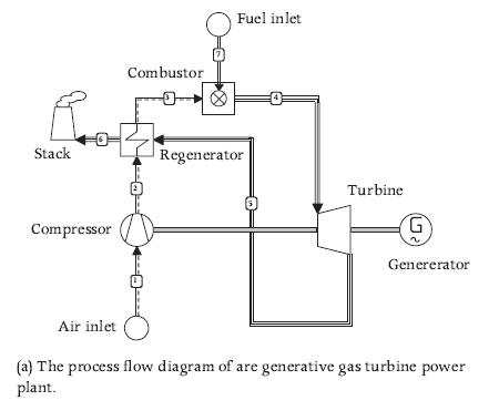
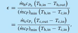
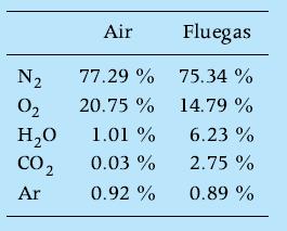
where subscripts h and c stand for the hot and the cold stream, respectively, and (m?cP)min is the smallest heat capacitance of these two streams. The isentropic efficiency of the compressor is 0.89 and that of the turbine is 0.92. The turbine inlet temperature is 1160?C. The mass flow of fuel entering the combustor is 0.36 kg/s and the lower heating value of the fuel is 38 MJ/kg (Dutch Slochteren natural gas). The air and exhaust gas composition are2
Assume that there are no pressure or thermal losses anywhere in the system and that no air is spilled from the compressor for turbine blade cooling. Determine the net mechanical power output in kW and the conversion efficiency of the system.
Stack Compressor Air inlet Combustor Fuel inlet Regenerator Turbine (12) G ~ Genererator (a) The process flow diagram of are generative gas turbine power plant.
Step by Step Solution
3.31 Rating (160 Votes )
There are 3 Steps involved in it
Air and exhaust gas thermodynamic properties are computed with GASMIX The notation is that of Figure ... View full answer

Get step-by-step solutions from verified subject matter experts