

Question: In Fig. 6.31b, resistive loads were used to extend the common-mode input range to include V EE . Fig. 6.62 shows another circuit with this
In Fig. 6.31b, resistive loads were used to extend the common-mode input range to include ˆ’VEE. Fig. 6.62 shows another circuit with this characteristic. Find the common-mode range of this circuit. Assume that VBE(on)= 0.7 V and VCE(sat)= 0.1 V for the npn transistors. Also, assume that VBE(on)= ˆ’ 0.7 V and VCE(sat)= ˆ’0.1 V for the pnp transistors. Ignore base currents for simplicity.
Fig. 6.31 b:
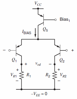
Fig. 6.62:
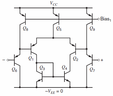
Vcc Bias, Qs IBIAS Q2 Q1 Vod VR2 R2 R1 VR1 -VEE = 0 Vcc Bias, Qs Q9 Q2 -o+ Q3 Q4 Q7 -VEE = 0
Step by Step Solution
★★★★★
3.37 Rating (172 Votes )
There are 3 Steps involved in it
1 Expert Approved Answer
Step: 1 Unlock

The upper end of the commonmode range is limited by saturation of Q 5 Either side of the circuit can ... View full answer
Question Has Been Solved by an Expert!
Get step-by-step solutions from verified subject matter experts
Step: 2 Unlock
Step: 3 Unlock
Document Format (2 attachments)
1528_605d88e1b6088_686903.pdf
180 KBs PDF File
1528_605d88e1b6088_686903.docx
120 KBs Word File