

Question: 1 This exercise explores the relationship between workspace and configuration space using the examples shown in Figure 32. a. Consider the robot configurations shown in
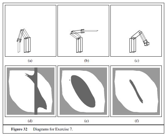
1 This exercise explores the relationship between workspace and configuration space using the examples shown in Figure 32.
a. Consider the robot configurations shown in Figure 32
(a) through (c), ignoring the obstacle shown in each of the diagrams. Draw the corresponding arm configurations in configuration space. (Hint: Each arm configuration maps to a single point in configuration space, as illustrated in Figure 14(b).)
b. Draw the configuration space for each of the workspace diagrams in Figure 32(a)–
(c). (Hint: The configuration spaces share with the one shown in Figure 32
(a) the region that corresponds to self-collision, but differences arise from the lack of enclosing obstacles and the different locations of the obstacles in these individual figures.)
c. For each of the black dots in Figure 32(e)–(f), draw the corresponding configurations of the robot arm in workspace. Please ignore the shaded regions in this exercise.
d. The configuration spaces shown in Figure 32(e)–
(f) have all been generated by a single workspace obstacle (dark shading), plus the constraints arising from the selfcollision constraint (light shading). Draw, for each diagram, the workspace obstacle that corresponds to the darkly shaded area.
e. Figure 32
(d) illustrates that a single planar obstacle can decompose the workspace into two disconnected regions. What is the maximum number of disconnected regions that can be created by inserting a planar obstacle into an obstacle-free, connected workspace, for a 2DOF robot? Give an example, and argue why no larger number of disconnected regions can be created. How about a non-planar obstacle?
(d) (b) 0 Figure 32 Diagrams for Exercise 7. (c) (f)
Step by Step Solution
There are 3 Steps involved in it

Get step-by-step solutions from verified subject matter experts