

Question: Modify the decoding circuit of Figure 12-35 to operate from a 16-line address bus (i.e., add A 13 , A 14 , and A 15
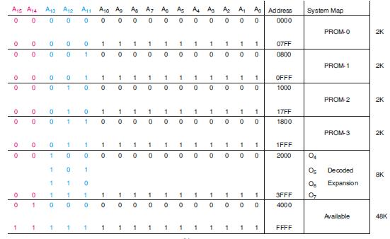
Modify the decoding circuit of Figure 12-35 to operate from a 16-line address bus (i.e., add A13, A14, and A15). The four PROMs are to maintain the same hex address ranges.
Figure 12-35
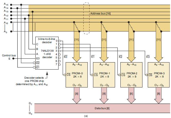
A15 A4 A13 A12 ..... A11 A10 Control bus E 3-line-to-8-line decoder C B A E3 decoder -OE2 01234567 Decoder selects one PROM chip determined by A and A 1b 74ALS138 3 1-of-8 00009999 2 b Ko CS Ao-A10 PROM-0 2K X 8 07-00 [8] T (a) Address bus [16] K1 CS [11] Ao-A PROM-1 2K X 8 07-00 [8] Data bus [8] K2 CS Ao-A10 PROM-2 2K x 8 07-00 [B] K3 Lacs [11] Ao-A10 PROM-3 2K X 8 07-0 [8]
Step by Step Solution
3.34 Rating (166 Votes )
There are 3 Steps involved in it

Get step-by-step solutions from verified subject matter experts