

Question: Consider the system shown in Figure 8.21, in which an RC high pass filter is followed by an ideal low pass filter having bandwidth W.
Consider the system shown in Figure 8.21, in which an RC high pass filter is followed by an ideal low pass filter having bandwidth W. Assume that the input to the system is A cos(2Ï€fct), where fc< W, plus white noise with double-sided power spectral density 1/2 N0. Determine the SNR at the output of the ideal low pass filter in terms of N0, A, R, C, W, and fc. What is the SNR in the limit as W †’ ˆž?
Figure 8.21
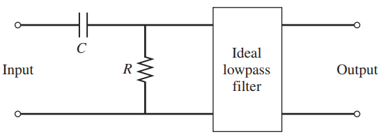
Ideal lowpass Input Output filter
Step by Step Solution
3.59 Rating (163 Votes )
There are 3 Steps involved in it
The transfer function of the RC high pass filter is so that Thus The PSD a... View full answer

Get step-by-step solutions from verified subject matter experts