Question
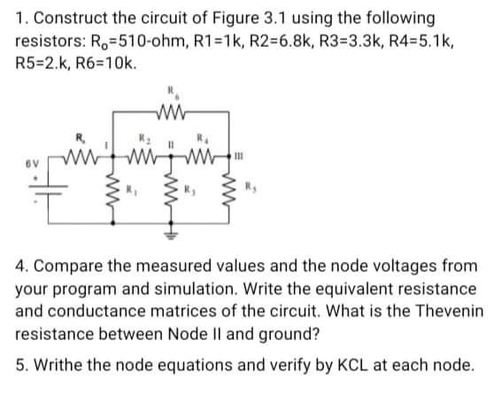
1. Construct the circuit of Figure 3.1 using the following resistors: R.-510-ohm, R1=1k, R236.8k, R3-3.3k, R4=5.1k, R5=2.k, R6=10k. ww 4. Compare the measured values

1. Construct the circuit of Figure 3.1 using the following resistors: R.-510-ohm, R1=1k, R236.8k, R3-3.3k, R4=5.1k, R5=2.k, R6=10k. ww 4. Compare the measured values and the node voltages from your program and simulation. Write the equivalent resistance and conductance matrices of the circuit. What is the Thevenin resistance between Node Il and ground? 5. Writhe the node equations and verify by KCL at each node.
Step by Step Solution
3.46 Rating (156 Votes )
There are 3 Steps involved in it
Step: 1
Construct The Circults using the given resister R 510R 2 1 k ...
Get Instant Access to Expert-Tailored Solutions
See step-by-step solutions with expert insights and AI powered tools for academic success
Step: 2

Step: 3

Ace Your Homework with AI
Get the answers you need in no time with our AI-driven, step-by-step assistance
Get StartedRecommended Textbook for
Electric Machinery
Authors: Charles Kingsley, Jr, Stephen D. Umans
6th Edition
71230106, 9780073660097, 73660094, 978-0071230100
Students also viewed these Electrical Engineering questions
Question
Answered: 1 week ago
Question
Answered: 1 week ago
Question
Answered: 1 week ago
Question
Answered: 1 week ago
Question
Answered: 1 week ago
Question
Answered: 1 week ago
Question
Answered: 1 week ago
Question
Answered: 1 week ago
Question
Answered: 1 week ago
Question
Answered: 1 week ago
Question
Answered: 1 week ago
Question
Answered: 1 week ago
Question
Answered: 1 week ago
Question
Answered: 1 week ago
Question
Answered: 1 week ago
Question
Answered: 1 week ago
Question
Answered: 1 week ago
Question
Answered: 1 week ago
Question
Answered: 1 week ago
Question
Answered: 1 week ago
Question
Answered: 1 week ago
Question
Answered: 1 week ago
View Answer in SolutionInn App


