

Question
1.Study the following circuit and write a truth table to describe the behavior. 2. Write a Verilog module called mystery to implement the circuit above.
1.Study the following circuit and write a truth table to describe the behavior.
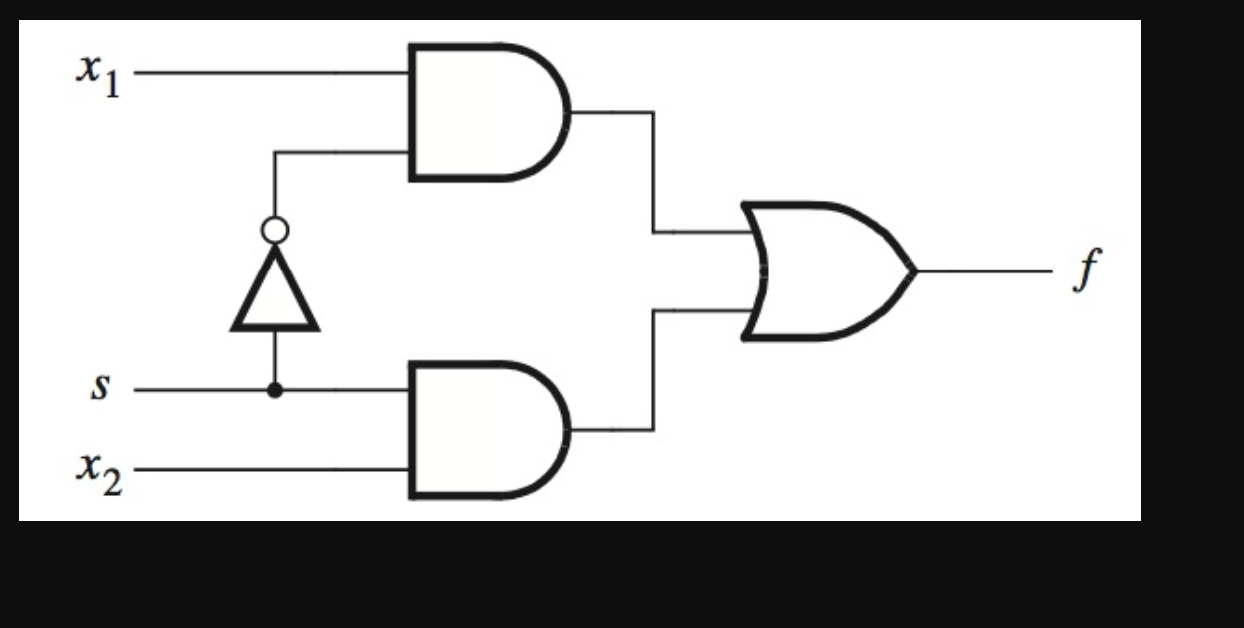
2. Write a Verilog module called mystery to implement the circuit above.
3.Write a test bench to fully test the mystery module created in step2.
4.Simulate the circuit using ISim and analyze the resulting waveform in comparison to the truth table from step 1
5.Take full screenshots of the source code of mystery module, the test bench Verilog file, and resulting simulation waveforms to be included in the lab report. Include your analysis of the resulting waveform to explain in detail how you can tell whether your Verilog implementation in Step 4 for the circuit is accurate
Step by Step Solution
There are 3 Steps involved in it
Step: 1

Get Instant Access to Expert-Tailored Solutions
See step-by-step solutions with expert insights and AI powered tools for academic success
Step: 2

Step: 3
Ace Your Homework with AI
Get the answers you need in no time with our AI-driven, step-by-step assistance
Get Started
Understanding Oracle APEX 5 Application Development
Authors: Edward Sciore
2nd Edition
1484209893, 9781484209899