Answered step by step
Verified Expert Solution
Question
1 Approved Answer
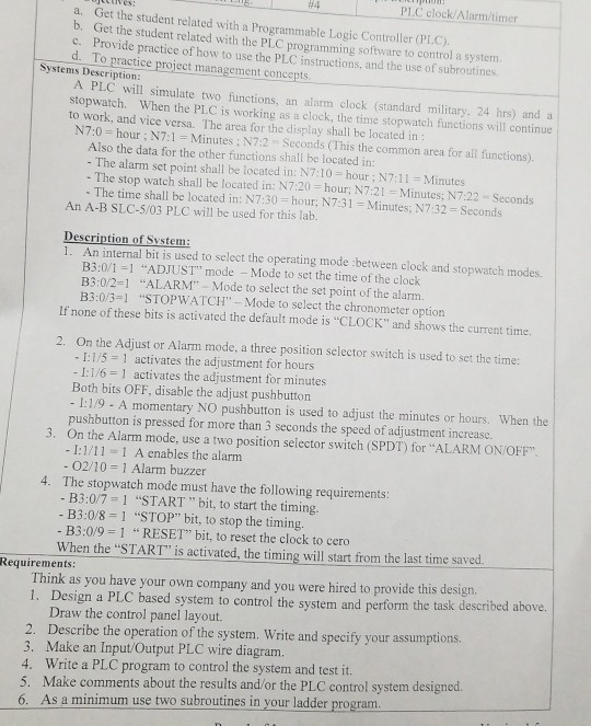
#4 PLC clock Ala me a. Get the student related with a Programmable Logic Controller (PL.C). b. Get the student related with the PLC programming


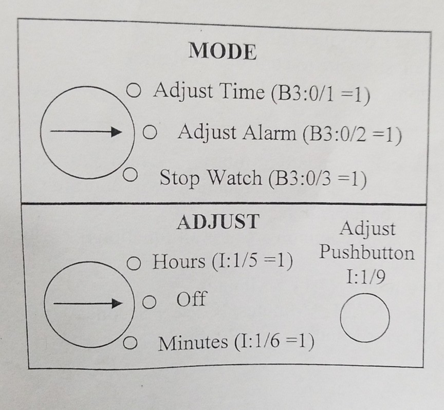
#4 PLC clock Ala me a. Get the student related with a Programmable Logic Controller (PL.C). b. Get the student related with the PLC programming software to control a system Provide practice of how to use the PLC instructions, and the use of subroutine d. To practice project management cone Systems Description PLC will simulate two functions, an alarm clock (standard military, 24 hrs) and a stopwatch. When the PL.C is working as a clock, the time stopwatch functions will continue to work, and vice versa. The area for the display shalil be located in N7:0 hour N7:1 Minutes ; N7:2 Seconds (This the common area for all functions). Also the data for the other functions shall be located in: - The alarm set point shall be located in: N7:10 hour; N7:11 Minutes The stop watch shall be located in: N7:20 hour, N7:21 Minutes; N7:22 Seconds The time shall be located in: N7:30-hour; N731 = Minutes; N7:32-Seconds An A-B SLC-5/03 PLC will be used for this lab An internal bit is used to select the operating mode :between clock and stopwatch modes B3:0/1-1 "ADJUST" mode -Mode to set the time of the clock B3:0/2-1 "ALARM" Mode to select the set point of the alarm B3:0/3-1 "STOPWATCH- Mode to select the chronometer option 1. If none of these bits is activated the default mode is "CLOCK" and shows the current time. 2. On the Adjust or Alarm mode, a three position selector switch is used to set the time I:1/5 activates the adjustment for hours I:1/6 1 activates the adjustment for minutes Both bits OFF, disable the adjust pushbutton I:1/9 - A momentary NO pushbutton is used to adjust the minutes or hours. When the pushbutton is pressed for more than 3 seconds the speed of adjustment increase. 3. On the Alarm mode, use a two position selector switch (SPDT) for "ALARM ON OFF" - I:1/11 1 A cnables the alarm 02/ 10 = 1 Alarm buzzer The stopwatch mode must have the following requirements: B3:0/7 1 "START" bit, to start the timing B3 :08-1 "STOP" bit, to stop the timing B3:0/9 1 RESET" bit, to reset the clock to cero 4. When the "START" is activated, the timing will start from the last time saved. Requirements: Think as you have your own company and you were hired to provide this design 1. Design a PLC based system to control the system and perform the task described above. Draw the control panel layout. 2. Describe the operation of the system. Write and specify your assumptions. 3. Make an Input/Output PLC wire diagram 4. Write a PLC program to control the system and test it 5. Make comments about the results and/or the PLC control system designed. 6. As a minimum use two subroutines in your ladder program MODE O Adjust Time (B3:0/1 -1) > | 0 Adjust Alarm (B3:0.2 = 1) O Stop Watch (B3:0/3-1) ADJUST Adjust O Hours (l:1/5-1) Pushbutton I:1/9 O Minutes (I:1/6-1) #4 PLC clock Ala me a. Get the student related with a Programmable Logic Controller (PL.C). b. Get the student related with the PLC programming software to control a system Provide practice of how to use the PLC instructions, and the use of subroutine d. To practice project management cone Systems Description PLC will simulate two functions, an alarm clock (standard military, 24 hrs) and a stopwatch. When the PL.C is working as a clock, the time stopwatch functions will continue to work, and vice versa. The area for the display shalil be located in N7:0 hour N7:1 Minutes ; N7:2 Seconds (This the common area for all functions). Also the data for the other functions shall be located in: - The alarm set point shall be located in: N7:10 hour; N7:11 Minutes The stop watch shall be located in: N7:20 hour, N7:21 Minutes; N7:22 Seconds The time shall be located in: N7:30-hour; N731 = Minutes; N7:32-Seconds An A-B SLC-5/03 PLC will be used for this lab An internal bit is used to select the operating mode :between clock and stopwatch modes B3:0/1-1 "ADJUST" mode -Mode to set the time of the clock B3:0/2-1 "ALARM" Mode to select the set point of the alarm B3:0/3-1 "STOPWATCH- Mode to select the chronometer option 1. If none of these bits is activated the default mode is "CLOCK" and shows the current time. 2. On the Adjust or Alarm mode, a three position selector switch is used to set the time I:1/5 activates the adjustment for hours I:1/6 1 activates the adjustment for minutes Both bits OFF, disable the adjust pushbutton I:1/9 - A momentary NO pushbutton is used to adjust the minutes or hours. When the pushbutton is pressed for more than 3 seconds the speed of adjustment increase. 3. On the Alarm mode, use a two position selector switch (SPDT) for "ALARM ON OFF" - I:1/11 1 A cnables the alarm 02/ 10 = 1 Alarm buzzer The stopwatch mode must have the following requirements: B3:0/7 1 "START" bit, to start the timing B3 :08-1 "STOP" bit, to stop the timing B3:0/9 1 RESET" bit, to reset the clock to cero 4. When the "START" is activated, the timing will start from the last time saved. Requirements: Think as you have your own company and you were hired to provide this design 1. Design a PLC based system to control the system and perform the task described above. Draw the control panel layout. 2. Describe the operation of the system. Write and specify your assumptions. 3. Make an Input/Output PLC wire diagram 4. Write a PLC program to control the system and test it 5. Make comments about the results and/or the PLC control system designed. 6. As a minimum use two subroutines in your ladder program MODE O Adjust Time (B3:0/1 -1) > | 0 Adjust Alarm (B3:0.2 = 1) O Stop Watch (B3:0/3-1) ADJUST Adjust O Hours (l:1/5-1) Pushbutton I:1/9 O Minutes (I:1/6-1)
Step by Step Solution
There are 3 Steps involved in it
Step: 1

Get Instant Access to Expert-Tailored Solutions
See step-by-step solutions with expert insights and AI powered tools for academic success
Step: 2

Step: 3

Ace Your Homework with AI
Get the answers you need in no time with our AI-driven, step-by-step assistance
Get Started


