Answered step by step
Verified Expert Solution
Question
1 Approved Answer
6. 7. 8. The lengths of various links of a mechanism, as shown in Fig. 6.32, are: OA = 0.3 m ; AB= 1
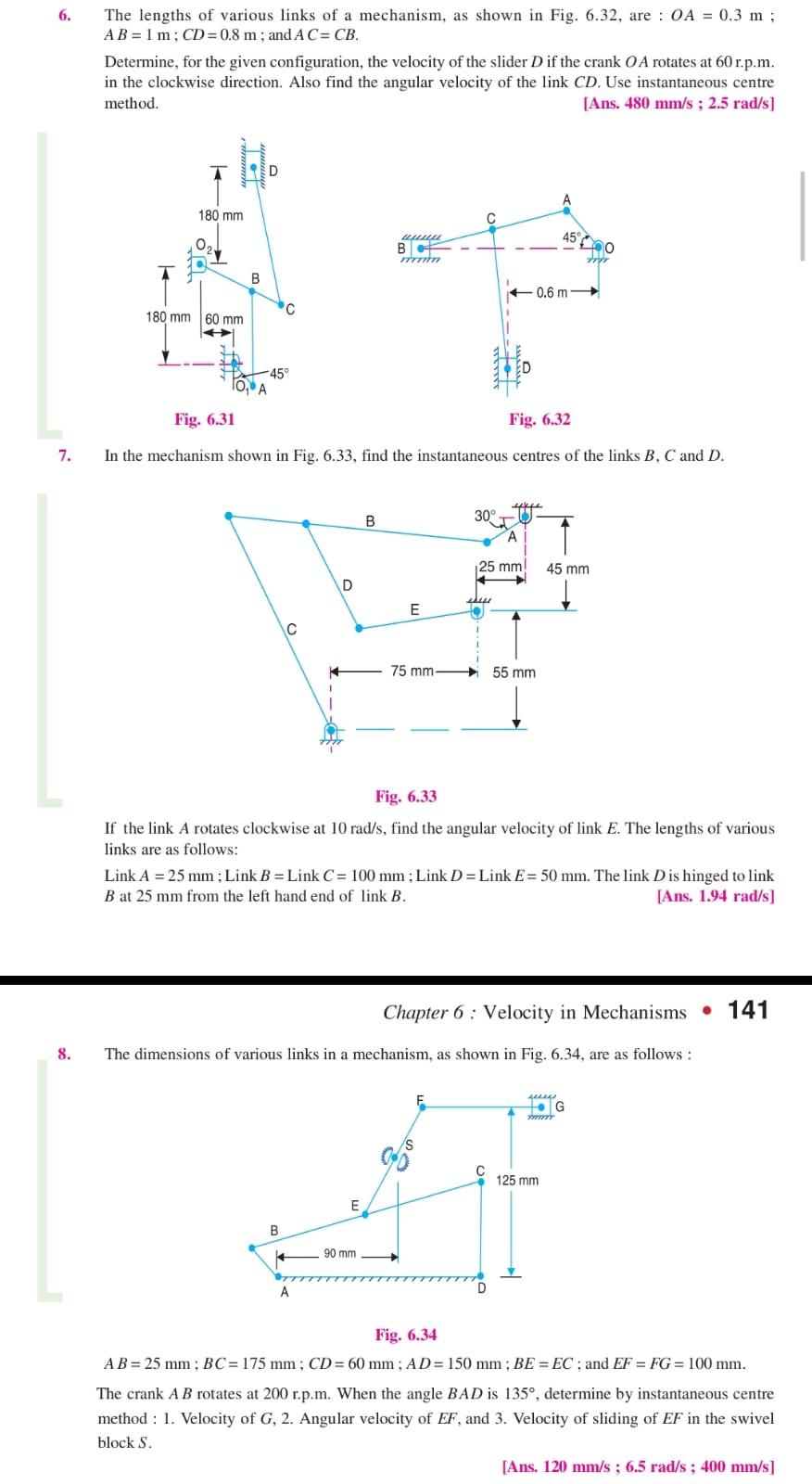
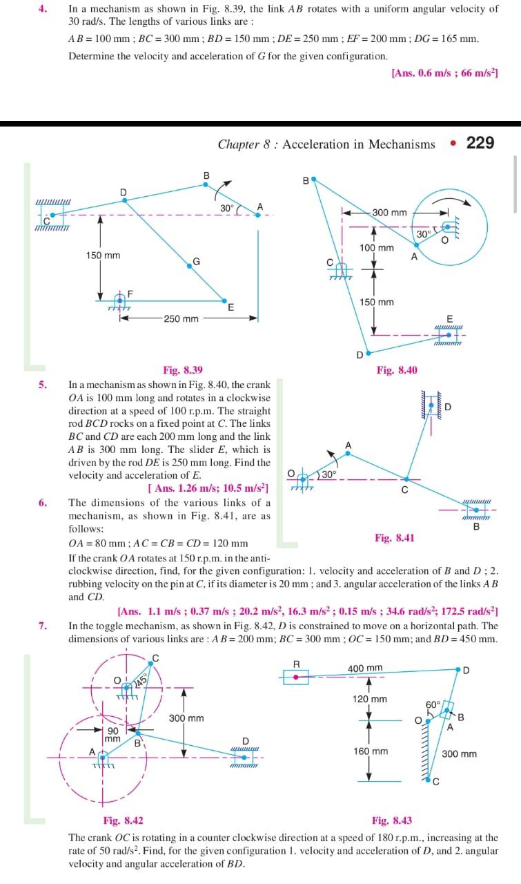
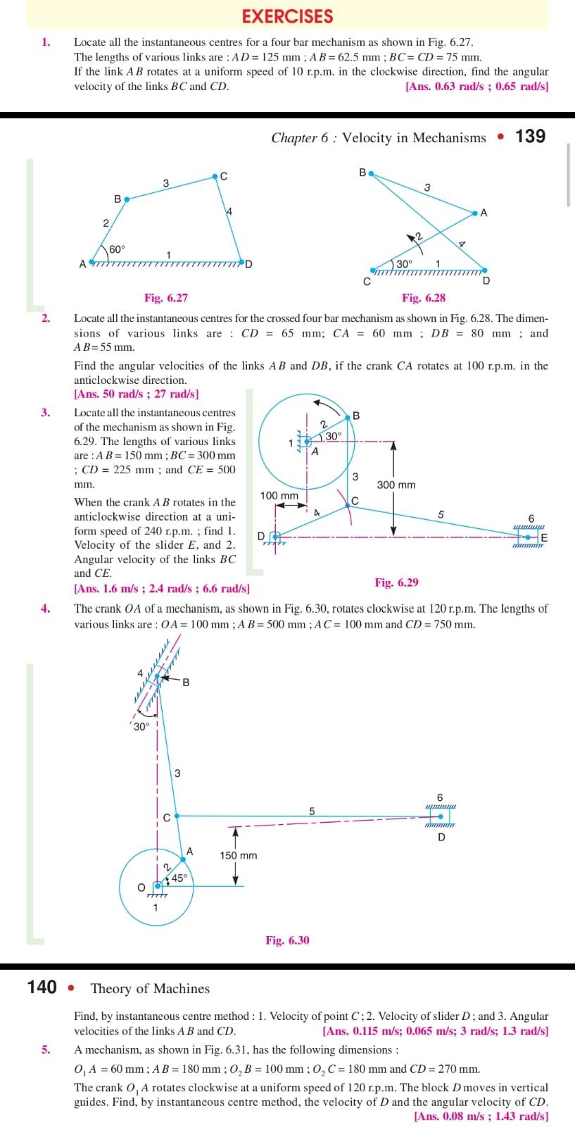
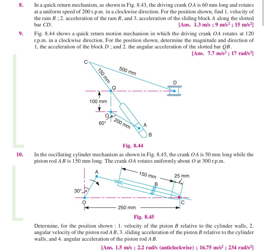
6. 7. 8. The lengths of various links of a mechanism, as shown in Fig. 6.32, are: OA = 0.3 m ; AB= 1 m; CD=0.8 m; and A C= CB. Determine, for the given configuration, the velocity of the slider D if the crank OA rotates at 60 r.p.m. in the clockwise direction. Also find the angular velocity of the link CD. Use instantaneous centre method. [Ans. 480 mm/s; 2.5 rad/s] 180 mm 0 180 mm 60 mm B D C -45 TO, A B D Fig. 6.31 Fig. 6.32 In the mechanism shown in Fig. 6.33, find the instantaneous centres of the links B, C and D. A wwww B Firm B E 90 mm E 75 mm- 30 O ww to Fig. 6.33 If the link A rotates clockwise at 10 rad/s, find the angular velocity of link E. The lengths of various links are as follows: 0.6 m Link A = 25 mm; Link B = Link C= 100 mm; Link D = Link E= 50 mm. The link D is hinged to link B at 25 mm from the left hand end of link B. [Ans. 1.94 rad/s] S A 25 mm 45 mm 45 55 mm The dimensions of various links in a mechanism, as shown in Fig. 6.34, are as follows: D Chapter 6: Velocity in Mechanisms 141 20 titr we 125 mm G Fig. 6.34 AB= 25 mm; BC= 175 mm; CD= 60 mm; AD= 150 mm; BE = EC; and EF = FG = 100 mm. The crank A B rotates at 200 r.p.m. When the angle BAD is 135, determine by instantaneous centre method: 1. Velocity of G, 2. Angular velocity of EF, and 3. Velocity of sliding of EF in the swivel block S. [Ans. 120 mm/s; 6.5 rad/s; 400 mm/s] 4. mmmmmm 5. 6. In a mechanism as shown in Fig. 8.39, the link AB rotates with a uniform angular velocity of 30 rad/s. The lengths of various links are : AB= 100 mm; BC = 300 mm; BD = 150 mm; DE = 250 mm; EF = 200 mm; DG = 165 mm. Determine the velocity and acceleration of G for the given configuration. 7. D 150 mm THEFT F O 90 mm itati 245 G Hi 250 mm B B Chapter 8: Acceleration in Mechanisms 229 30 300 mm E A D www B T- O -+*1. retr C Fig. 8.39 In a mechanism as shown in Fig. 8.40, the crank OA is 100 mm long and rotates in a clockwise direction at a speed of 100 r.p.m. The straight rod BCD rocks on a fixed point at C. The links BC and CD are each 200 mm long and the link AB is 300 mm long. The slider E, which is driven by the rod DE is 250 mm long. Find the velocity and acceleration of E. [ Ans. 1.26 m/s; 10.5 m/s] The dimensions of the various links of a mechanism, as shown in Fig. 8.41, are as follows: OA = 80 mm; AC=CB=CD= 120 mm If the crank OA rotates at 150 r.p.m. in the anti- clockwise direction, find, for the given configuration: 1. velocity and acceleration of B and D; 2. rubbing velocity on the pin at C, if its diameter is 20 mm; and 3. angular acceleration of the links A B and CD. R 14 30 300 mm 100 mm D [Ans. 0.6 m/s ; 66 m/s] 150 mm [Ans. 1.1 m/s; 0.37 m/s ; 20.2 m/s, 16.3 m/s; 0.15 m/s ; 34.6 rad/s; 172.5 rad/s] In the toggle mechanism, as shown in Fig. 8.42, D is constrained to move on a horizontal path. The dimensions of various links are: AB= 200 mm; BC = 300 mm; OC = 150 mm; and BD = 450 mm. Fig. 8.40 400 mm Fig. 8.41 120 mm 30 A C 160 mm E www Wo *+- mun O 60 www. D wwwwww -- www. B A D B 300 mm Fig. 8.42 Fig. 8.43 The crank OC is rotating in a counter clockwise direction at a speed of 180 r.p.m., increasing at the rate of 50 rad/s. Find, for the given configuration 1. velocity and acceleration of D, and 2. angular velocity and angular acceleration of BD. 1. 2. 3. 4. EXERCISES Locate all the instantaneous centres for a four bar mechanism as shown in Fig. 6.27. The lengths of various links are: AD= 125 mm; AB= 62.5 mm; BC= CD = 75 mm. If the link A B rotates at a uniform speed of 10 r.p.m. in the clockwise direction, find the angular velocity of the links BC and CD. [Ans. 0.63 rad/s; 0.65 rad/s] 5. 2 A 177 B 60 140. 3 Locate all the instantaneous centres of the mechanism as shown in Fig. 6.29. The lengths of various links are: A B = 150 mm; BC= 300 mm ; CD = 225 mm; and CE = 500 mm. 4 When the crank AB rotates in the anticlockwise direction at a uni- form speed of 240 r.p.m.; find 1. Velocity of the slider E, and 2. Angular velocity of the links BC and CE. [Ans. 1.6 m/s ; 2.4 rad/s; 6.6 rad/s] '30! 1 1 C Fig. 6.27 Fig. 6.28 Locate all the instantaneous centres for the crossed four bar mechanism as shown in Fig. 6.28. The dimen- sions of various links are CD= 65 mm; CA = 60 mm; DB = 80 mm; and AB=55 mm. 2 C Find the angular velocities of the links AB and DB, if the crank CA rotates at 100 r.p.m. in the anticlockwise direction. [Ans. 50 rad/s; 27 rad/s] Hiti 1 4 3 777777777D B A 45 Chapter 6: Velocity in Mechanisms 139 150 mm 100 mm D 2 A 5 Fig. 6.30 Be 30 Fig. 6.29 The crank OA of a mechanism, as shown in Fig. 6.30, rotates clockwise at 120 r.p.m. The lengths of various links are: OA = 100 mm; A B = 500 mm; AC= 100 mm and CD= 750 mm. B 3 30 C 2 3 300 mm 5 A D 6 ww t wwwmin D 6 www E mmmmmmm Theory of Machines Find, by instantaneous centre method: 1. Velocity of point C; 2. Velocity of slider D; and 3. Angular velocities of the links A B and CD. [Ans. 0.115 m/s; 0.065 m/s; 3 rad/s; 1.3 rad/s] A mechanism, as shown in Fig. 6.31, has the following dimensions: 0 A = 60 mm; AB = 180 mm; O B = 100 mm; 0 C = 180 mm and CD = 270 mm. The crank O, A rotates clockwise at a uniform speed of 120 r.p.m. The block D moves in vertical guides. Find, by instantaneous centre method, the velocity of D and the angular velocity of CD. [Ans. 0.08 m/s ; 1.43 rad/s] 8. 9. 10. In a quick return mechanism, as shown in Fig. 8.43, the driving crank OA is 60 mm long and rotates at a uniform speed of 200 r.p.m. in a clockwise direction. For the position shown, find 1. velocity of the ram R; 2. acceleration of the ram R, and 3. acceleration of the sliding block A along the slotted bar CD. [Ans. 1.3 m/s ; 9 m/s; 15 m/s] Fig. 8.44 shows a quick return motion mechanism in which the driving crank OA rotates at 120 r.p.m. in a clockwise direction. For the position shown, determine the magnitude and direction of 1, the acceleration of the block D; and 2. the angular acceleration of the slotted bar QB. [Ans. 7.7 m/s; 17 rad/s] 150 mm 30 100 mm 60 500 mm 200 mm A 250 mm B Fig. 8.44 In the oscillating cylinder mechanism as shown in Fig. 8.45, the crank OA is 50 mm long while the piston rod A B is 150 mm long. The crank OA rotates uniformly about O at 300 r.p.m. 150 mm D wwwww B /www/w 25 mm Fig. 8.45 Determine, for the position shown : 1. velocity of the piston B relative to the cylinder walls, 2. angular velocity of the piston rod A B, 3. sliding acceleration of the piston B relative to the cylinder walls, and 4. angular acceleration of the piston rod A B. [Ans. 1.5 m/s ; 2.2 rad/s (anticlockwise) ; 16.75 m/s ; 234 rad/s]
Step by Step Solution
★★★★★
3.43 Rating (159 Votes )
There are 3 Steps involved in it
Step: 1
I15 113 I13 135 116 I56 I12 I 23 I4 134 1 16 ...
Get Instant Access to Expert-Tailored Solutions
See step-by-step solutions with expert insights and AI powered tools for academic success
Step: 2

Step: 3

Ace Your Homework with AI
Get the answers you need in no time with our AI-driven, step-by-step assistance
Get Started


