Answered step by step
Verified Expert Solution
Link Copied!

Question

1 Approved Answer

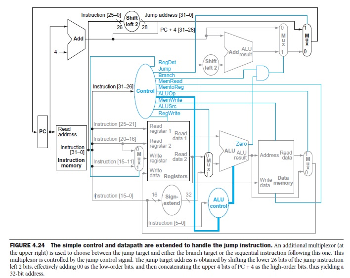
Assume we want to execute the following new instruction on the given MIPS single-cycle data path figure below. mov R[rt], R[rs]; This instruction uses I-format

Assume we want to execute the following new instruction on the given MIPS single-cycle data path figure below.

mov R[rt], R[rs]; This instruction uses I-format and performs: R[rt] R[rs]

The opcode of the mov instruction is 001001. Modify the data path and identify the values of the following control signals needed for this instruction. Then modify the control unit to implement the control signals. Assume that you are not allowed to change ALU operations.

RegDst

ALUSrc

MemtoReg

RegWrite

MemRead

MemWrite

Newsignal

image text in transcribed

instruction [25-0] Jump address (31-0 Shift 26 left 2 28 PC 4 (31-281 Add Add result Shift left 2 Jump Branch MemRead Instruction [31-26] MemtoReg Control ALU em ALUSrc RegWrite Read -l nstruction [25-21] register 1 Read address Instruction 120-16] Read data 1 register 2 Instruction ALU ALU Address data M 131-01 M data 2 register Instruction nstruction [15-11] X memory data Registers Data data memory truction [15-0] 16 Sign- 32 ALU extend Instruction [5-0] FIGURE 4.24 The simple control and datapath are extended to handle the jump instruction An additional multiplexor (at the upper right) is used to choose between the jump target and either the branch target or the sequential instruction following this one. This multiplexor is controlled by the jump control signal. The jump target address is obtained by shifting the lower 26 bits ofthe jump instruction left 2 bits, effectively adding 00 as the low-order bits, and then concatenating the upper 4 bits of PC 4 as the high-order bits, thus yielding a 32-bit address. instruction [25-0] Jump address (31-0 Shift 26 left 2 28 PC 4 (31-281 Add Add result Shift left 2 Jump Branch MemRead Instruction [31-26] MemtoReg Control ALU em ALUSrc RegWrite Read -l nstruction [25-21] register 1 Read address Instruction 120-16] Read data 1 register 2 Instruction ALU ALU Address data M 131-01 M data 2 register Instruction nstruction [15-11] X memory data Registers Data data memory truction [15-0] 16 Sign- 32 ALU extend Instruction [5-0] FIGURE 4.24 The simple control and datapath are extended to handle the jump instruction An additional multiplexor (at the upper right) is used to choose between the jump target and either the branch target or the sequential instruction following this one. This multiplexor is controlled by the jump control signal. The jump target address is obtained by shifting the lower 26 bits ofthe jump instruction left 2 bits, effectively adding 00 as the low-order bits, and then concatenating the upper 4 bits of PC 4 as the high-order bits, thus yielding a 32-bit address

Step by Step Solution

There are 3 Steps involved in it

Step: 1

blur-text-image

Get Instant Access to Expert-Tailored Solutions

See step-by-step solutions with expert insights and AI powered tools for academic success

Step: 2

blur-text-image

Step: 3

blur-text-image

Ace Your Homework with AI

Get the answers you need in no time with our AI-driven, step-by-step assistance

Get Started

Recommended Textbook for

Professional Microsoft SQL Server 2012 Administration

Authors: Adam Jorgensen, Steven Wort

1st Edition

1118106881, 9781118106884

More Books

Students also viewed these Databases questions