Question
CLEAR MACRO R1, C1, R2, C2 MOV AX, 0600H MOV BH, 07H MOV CH, R1 MOV CL, C1 MOV DH, R2 MOV DL, C2 INT

CLEAR MACRO R1, C1, R2, C2
MOV AX, 0600H
MOV BH, 07H
MOV CH, R1
MOV CL, C1
MOV DH, R2
MOV DL, C2
INT 10H
ENDM
DISPSTR MACRO STR
MOV AH, 09H
MOV DX, OFFSET STR
INT 21H
ENDM
;THIS IS THE MACRO USED FOR ROTATING THE MOTOR AND ALSO DISPLAYING TO THE 7 SGEMENT;
ROTATE MACRO BYTE, DIRECTION
LOCAL LEFT,OVER
MOV AL, BYTE
MOV BH,[SI]
AND BH, 00001111B
AND AL, 11110000B
MOV BL,AL
MOV CL,4
SHR AL,CL
ADD AL, BL
MOV AH, DIRECTION
CMP AH, 01H
JE LEFT
ROR AL,1
JMP OVER
LEFT: ROL AL,1
OVER:AND AL,11110000B
ADD AL,BH
MOV CX,[DI]
MOV DX, 0378H
OUT DX, AL
PUSH AX
CALL WAITF
ENDM
SETCUR MACRO R, C
MOV AH, 02H
MOV BH, 00H
MOV DH, R
MOV DL, C
INT 10H
ENDM
.MODEL SMALL
.STACK 64
.DATA
MSG1 DB 'EENG410 Project done by Michee, Anaab and Ahmed$'
MSG2 DB 'left click mouse to rotate clockwise$'
MSG3 DB 'right click to mouse rotate anticlockwise$'
MSG4 DB 'press u/U to speed up$'
MSG5 DB 'press d/D to slow down$'
MSG10 DB 'press q/Q to exit$'
MSG6 DB 'Rotation:$'
MSG7 DB 'Speed:$'
MSG8 DB 'Clockwise$'
MSG9 DB 'Anti-Clockwise$'
LEVEL DB '01234567'
DELAY DW 65535,10000,6500,5500,4500,3500,2500,2200
.CODE
MAIN: MOV AX, @DATA
MOV DS, AX
CLEAR 00,00,24,79
MOV SI, OFFSET LEVEL
MOV DI, OFFSET DELAY
SETCUR 01H, 01H
DISPSTR MSG1
SETCUR 02H, 01H
DISPSTR MSG2
SETCUR 03H, 01H
DISPSTR MSG3
SETCUR 04H, 01H
DISPSTR MSG4
SETCUR 05H, 01H
DISPSTR MSG5
SETCUR 06H, 01H
DISPSTR MSG10
SETCUR 07H, 01H
DISPSTR MSG6
SETCUR 08H, 01H
DISPSTR MSG7
MOV AX,0006H
PUSH AX
;HERE IS THE FUNCTION WHERE, WHEN THE MOUSE IS RIGHT CLICKED IT GOES TO THE ROTATE MACRO AND TURNS THE MOTOR CLOCKWISE AND VICE VERSA;
REPEAT: MOV AX, 0003H
INT 33H
CMP BX,0001H
JE ANTICLOCKWISE
CMP BX,0002H
JE CLOCKWISE
JMP HERE
ANTICLOCKWISE: CLEAR 07H,12H,07H,2BH
SETCUR 07H, 12H
DISPSTR MSG8
ROTATE 33H,01H
JMP HERE
CLOCKWISE: CLEAR 07H,12H,07H,2BH
SETCUR 07H,12H
DISPSTR MSG9
ROTATE 33H,00H
; THIS IS WHERE, WHEN YOU PRESS THE LETTERS AS SHOWN BELOW IT DIRECTS IT TO SPEEDING UP(U/u), LOWERING THE SPEEDS (D/u) ADN QUITING (Q/q);
HERE: POP AX
ROTATE AL, AH
MOV AH, 01H
INT 16H
JZ AGAIN
MOV AH, 00H
INT 16H
CMP AL, 'Q'
JE EXIT
CMP AL, 'q'
JE EXIT
CMP AL, 'U'
JE UP
CMP AL, 'u'
JE UP
CMP AL, 'D'
JE DOWN
CMP AL, 'd'
JE DOWN
JMP AGAIN
;THE SPEEDS ARE INCREMENTED/INCREASED;
UP: SETCUR 08H, 08H
MOV AL, [SI]
CMP AL, '7'
JE OUTPUT
ABOVE: INC SI
INC DI
INC DI
;THIS IS THE DISPLAYING IN THE MONITOR FOR THE INCREMENTED SPEED;
OUTPUT: MOV AH, 02H
MOV DL,[SI]
INT 21H
JMP AGAIN
;SPEEDS ARE DECREMENTED/DECREASED;
DOWN: SETCUR 08H, 08H
MOV AL, [SI]
CMP AL, '.'
JE ABOVE
MOV AL, [SI]
CMP AL, '0'
JE SAME
DEC SI
DEC DI
DEC DI
;THIS IS THE DISPLAYING IN THE MONITOR FOR THE DECREMENTED SPEED;
SAME: MOV AH,02H
MOV DL, [SI]
INT 21H
AGAIN: JMP REPEAT
EXIT: MOV AH, 4CH
INT 21H
WAITF: PUSH AX
WAITF1: IN AL, 61H
AND AL, 10H
CMP AL,AH
JE WAITF1
MOV AH,AL
LOOP WAITF1
POP AX
RET
END MAIN (This is the code that I currently have, this code currently changes the speed from the keyboard and changes the rotation direction from the mouse. I just want it the other way around were I change the rotation direction from the keyboard, and changing the speed of the motor using left and right click) We are using ULN2003A stepper 5V motor Seven segment display IC 7447
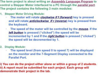
The term project is about writing an Assembly Language Program to control a Stepper Motor interfaced to a PC through the parallel port The project contains the following 3 main modules: 1. Stepper Motor Driving Module: The motor will rotate clockwise iff (forward) key is pressed and will rotate anticlockwise ifr (reverse) key is pressed from the keyboard. The speed of the motor will be controlled by the mouse. If the left button is pressed ("clicked") the speed will be incremented by 1 and If the right button is pressed ("clicked") the speed will be decremented by 1. 2. Display Module: The speed level (from speed 0 to speed 7) will be displayed on the monitor and the 7-Segment Display connected to the Parallel Port. i) You can do the project either alone or within a group of 2 students. ii) A report must be submitted for each project. Each group will demonstrate their project in the lab. The term project is about writing an Assembly Language Program to control a Stepper Motor interfaced to a PC through the parallel port The project contains the following 3 main modules: 1. Stepper Motor Driving Module: The motor will rotate clockwise iff (forward) key is pressed and will rotate anticlockwise ifr (reverse) key is pressed from the keyboard. The speed of the motor will be controlled by the mouse. If the left button is pressed ("clicked") the speed will be incremented by 1 and If the right button is pressed ("clicked") the speed will be decremented by 1. 2. Display Module: The speed level (from speed 0 to speed 7) will be displayed on the monitor and the 7-Segment Display connected to the Parallel Port. i) You can do the project either alone or within a group of 2 students. ii) A report must be submitted for each project. Each group will demonstrate their project in the labStep by Step Solution
There are 3 Steps involved in it
Step: 1

Get Instant Access to Expert-Tailored Solutions
See step-by-step solutions with expert insights and AI powered tools for academic success
Step: 2

Step: 3

Ace Your Homework with AI
Get the answers you need in no time with our AI-driven, step-by-step assistance
Get Started


