Answered step by step
Verified Expert Solution
Question
1 Approved Answer
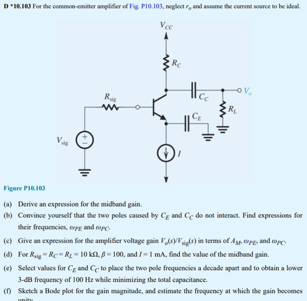
D *10.103 For the common-emitter amplifier of Fig. P10.103, neglectr, and assume the current source to be ideal. Vsig Rig www Vcc Rc 1

D *10.103 For the common-emitter amplifier of Fig. P10.103, neglectr, and assume the current source to be ideal. Vsig Rig www Vcc Rc 1 tl Cc CE OV RL Figure P10.103 (a) Derive an expression for the midband gain. (b) Convince yourself that the two poles caused by CE and Cc do not interact. Find expressions for their frequencies, @PE and PC. (c) Give an expression for the amplifier voltage gain Vo(s)/Vsig(s) in terms of AM, OPE, and PC. (d) For Rsig = Rc = R = 10 ks2, B = 100, and I = 1 mA, find the value of the midband gain. (e) Select values for Cg and Cc to place the two pole frequencies a decade apart and to obtain a lower 3-dB frequency of 100 Hz while minimizing the total capacitance. (f) Sketch a Bode plot for the gain magnitude, and estimate the frequency at which the gain becomes unity
Step by Step Solution
★★★★★
3.34 Rating (166 Votes )
There are 3 Steps involved in it
Step: 1
a So The equivalent circuit would be given as Calculation As per ...
Get Instant Access to Expert-Tailored Solutions
See step-by-step solutions with expert insights and AI powered tools for academic success
Step: 2

Step: 3

Ace Your Homework with AI
Get the answers you need in no time with our AI-driven, step-by-step assistance
Get Started


