Answered step by step
Verified Expert Solution
Question
1 Approved Answer
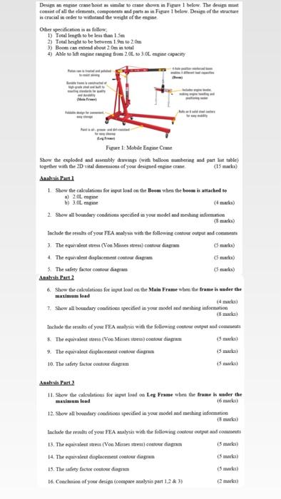
Design an engine crane/hoist as similar to crane shown in Figure 1 below. The design must consist of all the elements, components and parts as
Design an engine crane/hoist as similar to crane shown in Figure 1 below. The design must consist of all the elements, components and parts as in Figure 1 below. Design of the structure is crucial in order to withstand the weight of the engine. Other specification is as follow; 1) Total length to be less than ( 1.5 mathrm{~m} ) 2) Total height to be between ( 1.9 mathrm{~m} ) to ( 2.0 mathrm{~m} ) 3) Boom can extend about ( 2.0 mathrm{~m} ) in total 4) Able to lift engine ranging from ( 2.0 mathrm{~L} ) to ( 3.0 mathrm{~L} ) engine capacity Figure 1: Mobile Engine Crane Show the exploded and assembly drawings (with balloon numbering and part list table) together with the ( 2 mathrm{D} ) vital dimensions of your designed engine crane. (15 marks) Analvsis Part 1 1. Show the calculations for input load on the Boom when the boom is attached to a) ( 2.0 mathrm{~L} ) engine b) 3.0L engine (4 marks) 2. Show all boundary conditions specified in your model and meshing information (8 marks) Include the results of your FEA analysis with the following contour output and comments Anarysis cane 2 6. Show the calculations for input load on the Main Frame when the frame is under the maximum load (4 marks) 7. Show all boundary conditions specified in your model and meshing information (8 marks) Include the results of your FEA analysis with the following contour output and comments 8. The equivalent stress (Von Misses stress) contour diagram (5 marks) 9. The equivalent displacement contour diagram (5 marks) 10. The safety factor contour diagram (5 marks) Analysis Part 3 11. Show the calculations for input load on Leg Frame when the frame is under the maximum load (6 marks) 12. Show all boundary conditions specified in your model and meshing information (8 marks) Include the results of your FEA analysis with the following contour output and comments 13. The equivalent stress (Von Misses stress) contour diagram (5 marks) 14. The equivalent displacement contour diagram (5 marks) 15. The safety factor contour diagram (5 marks) 16. Conclusion of your design (compare analysis part ( 1,2 & 3 ) ) (2 marks)

Design an engine crane hoist as similar to crane shown in Figure 1 below. The design must consist of all the elements, components and parts as in Figure 1 below. Design of the structure is crucial in order to withstand the weight of the engine Other specification is as follow 1) Total length to be less than 1.5m 2) Total height to be between 1.9m to 2.0m 3) Boom can extend about 2.0m in total 4) Able to lift engine ranging from 2.0 to 3.0L engine capacity Figure 1: Mobile Engine Crane Show the exploded and assembly drawings (with balloon numbering and part list table) together with the 2D vital dimensions of your designed engine crane (15 marks) Aaahsis Part 1 1. Show the calculations for input load on the Boom when the boom is attached to a) 2.0L engine b) 3.0L engine (4 marks) 2. Show all boundary conditions specified in your model and meshing information (8 marks) Include the results of your FEA analysis with the following contour output and comments 3. The equivalent stress (Von Misses stress) contour diagram (5 marks) 4. The equivalent displacement contour diagram 5. The safety factor contour diagram Analysis Part 2 6. Show the calculations for input load on the Main Frame when the frame is under the maximum load (5 marks) (5 marks) (4 marks) 7. Show all boundary conditions specified in your model and meshing information (8 marks) Include the results of your FEA analysis with the following contour output and comments 8. The equivalent stress (Von Misses stress) contour diagram (5 marks) 9. The equivalent displacement contour diagram 10. The safety factor contour diagram (5 marks) (5 marks) Analysis Part 3 11. Show the calculations for input load on Leg Frame when the frame is under the maximum load (6 marks) 12. Show all boundary conditions specified in your model and meshing information (8 marks) Include the results of your FEA analysis with the following contour output and comments 13. The equivalent stress (Von Misses stress) como diagram (5 marks) 14. The equivalent displacement contour diagram 15. The safety factor contour diagram (5 marks) (5 marks) 16. Conclusion of your design (compare analysis part 1,2 & 3) (2 marks)
Step by Step Solution
There are 3 Steps involved in it
Step: 1

Get Instant Access to Expert-Tailored Solutions
See step-by-step solutions with expert insights and AI powered tools for academic success
Step: 2

Step: 3

Ace Your Homework with AI
Get the answers you need in no time with our AI-driven, step-by-step assistance
Get Started


