Answered step by step
Verified Expert Solution
Question
1 Approved Answer
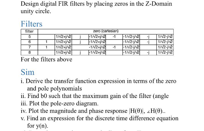
Design digital FIR filters by placing zeros in the Z-Domain unity circle. Filters filter 5 6 7 8 1/2+j/v2 j 1 1/2+j/2 1 1//2+j/2


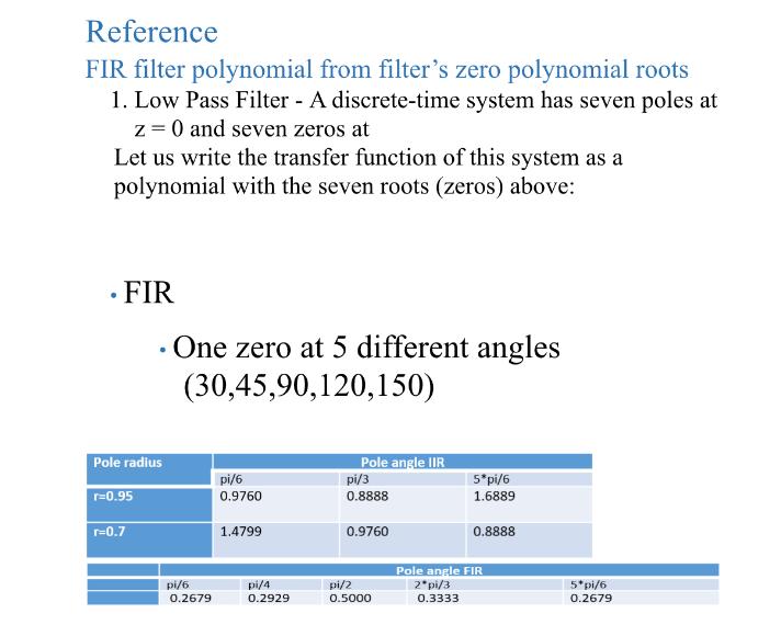
Design digital FIR filters by placing zeros in the Z-Domain unity circle. Filters filter 5 6 7 8 1/2+j/v2 j 1 1/2+j/2 1 1//2+j/2 zero (cartesian) -1/2+j/2 -1 -1/2-j/v2 -j 1/2-1/v2 -1/2+j/2 -1//2-1/2 j 1/2-j/2 -1//2+j/v2 -1 -1//2-j/2 1/2-j/v2 -1//2-1/2 -j 1/2-j/v/2 1//2+j/2 j -1//2+j/2 For the filters above Sim i. Derive the transfer function expression in terms of the zero and pole polynomials ii. Find b0 such that the maximum gain of the filter (angle iii. Plot the pole-zero diagram. iv. Plot the magnitude and phase response H(0)|, ZH(0).. v. Find an expression for the discrete time difference equation for y(n). Reference FIR filter polynomial from filter's zero polynomial roots 1. Low Pass Filter - A discrete-time system has seven poles at z = 0 and seven zeros at Let us write the transfer function of this system as a polynomial with the seven roots (zeros) above: FIR Pole radius r=0.95 r=0.7 One zero at 5 different angles (30,45,90,120,150) pi/6 0.2679 pi/6 0.9760 1.4799 pi/4 0.2929 Pole angle IIR pi/3 0.8888 0.9760 pi/2 0.5000 5*pi/6 1.6889 0.8888 Pole angle FIR 2*pi/3 0.3333 5*pi/6 0.2679
Step by Step Solution
There are 3 Steps involved in it
Step: 1

Get Instant Access to Expert-Tailored Solutions
See step-by-step solutions with expert insights and AI powered tools for academic success
Step: 2

Step: 3

Ace Your Homework with AI
Get the answers you need in no time with our AI-driven, step-by-step assistance
Get Started


