Answered step by step
Verified Expert Solution
Question
1 Approved Answer
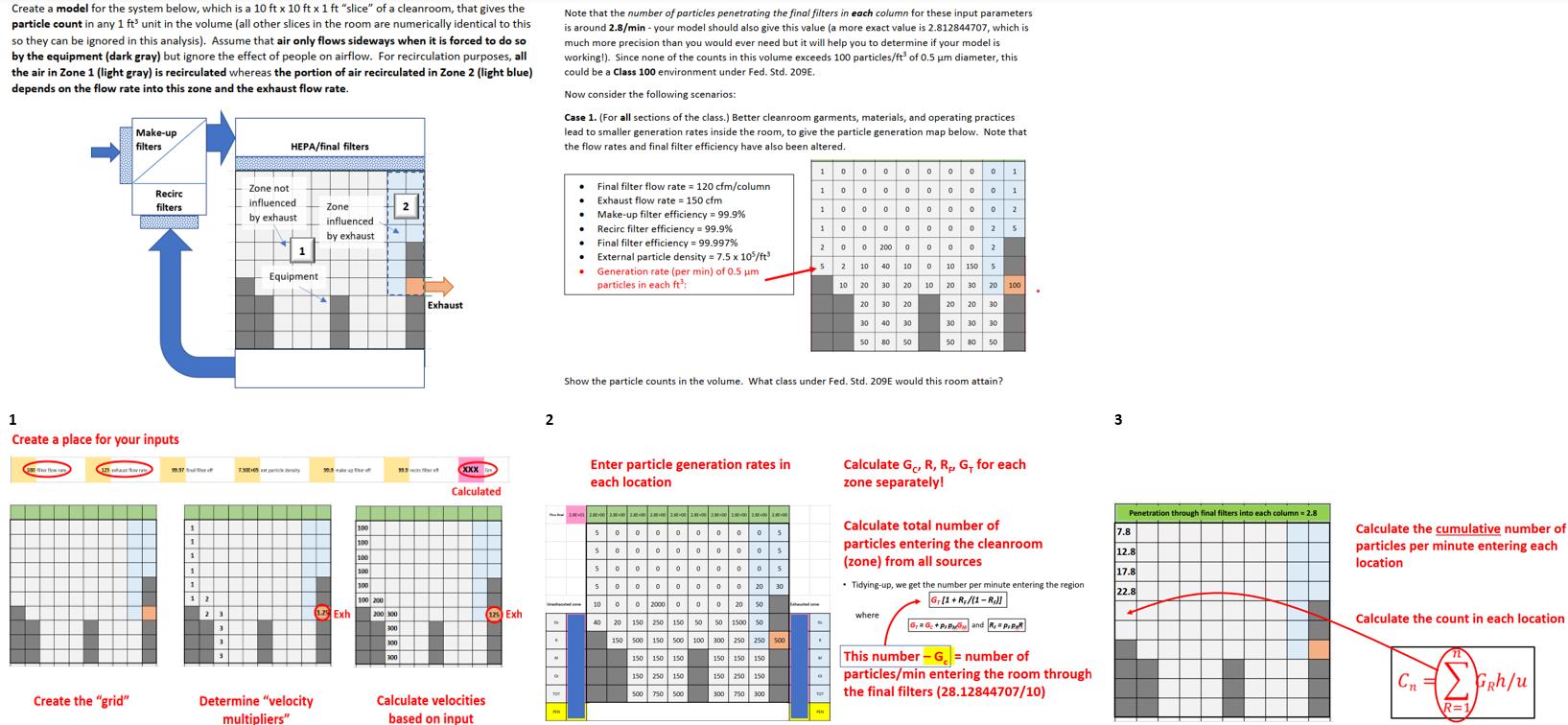
Create a model for the system below, which is a 10 ft x 10 ft x 1ft slice of a cleanroom, that gives the

Create a model for the system below, which is a 10 ft x 10 ft x 1ft "slice" of a cleanroom, that gives the particle count in any 1 ft' unit in the volume (all other slices in the room are numerically identical to this so they can be ignored in this analysis). Assume that air only flows sideways when it is forced to do so by the equipment (dark gray) but ignore the effect of people on airflow. For recirculation purposes, all the air in Zone 1 (light gray) is recirculated whereas the portion of air recirculated in Zone 2 (light blue) depends on the flow rate into this zone and the exhaust flow rate. Make-up filters HEPA/final filters Note that the number of particles penetrating the final filters in each column for these input parameters is around 2.8/min - your model should also give this value (a more exact value is 2.812844707, which is much more precision than you would ever need but it will help you to determine if your model is working!). Since none of the counts in this volume exceeds 100 particles/ft of 0.5 m diameter, this could be a Class 100 environment under Fed. Std. 209E. Now consider the following scenarios: Case 1. (For all sections of the class.) Better cleanroom garments, materials, and operating practices lead to smaller generation rates inside the room, to give the particle generation map below. Note that the flow rates and final filter efficiency have also been altered. 1 0 0 0 0 0 0 0 0 1 Final filter flow rate = 120 cfm/column Recirc filters Zone not influenced by exhaust Exhaust flow rate 150 cfm 2 Zone influenced by exhaust Make-up filter efficiency = 99.9% 1 0 0 0 0 0 0 0 0 1 1000000002 1000000025 Recirc filter efficiency = 99.9% Final filter efficiency = 99.997% 1 Equipment External particle density = 7.5 x 10⁵/ft Generation rate (per min) of 0.5 m particles in each ft: 200 200 00002 5 2 10 40 10 0 10 150 5 10 20 30 20 10 20 30 20 100 1 Create a place for your inputs 7.300 100 1 100 1 100 1 100 1 100 100 200 Exh 3 3 Exhaust XXX Calculated 125 Exh 300 300 300 2 20 30 20 20 20 30 30 40 30 30 30 30 50 80 50 50 80 50 Show the particle counts in the volume. What class under Fed. Std. 209E would this room attain? Enter particle generation rates in each location 5000000005 5000000005 5000000005 500000002030 10002000000 20 50 Calculate G, R, R, G+ for each zone separately! 3 Penetration through final filters into each column = 2.8 Calculate total number of 7.8 particles entering the cleanroom 12.8 (zone) from all sources Calculate the cumulative number of particles per minute entering each location 17.8 Tidying-up, we get the number per minute entering the region G.[1+R,/(1-R,)] 22.8 where 20 150 250 150 50 50 1500 50 150 500 150 500 100 300 250 250 500 This number-G = number of particles/min entering the room through the final filters (28.12844707/10) 150 150 150 150 150 150 150 250 150 500 750 500 300 750 300 Create the "grid" Determine "velocity Calculate velocities multipliers" based on input Calculate the count in each location C R=1 GRh/u
Step by Step Solution
There are 3 Steps involved in it
Step: 1

Get Instant Access to Expert-Tailored Solutions
See step-by-step solutions with expert insights and AI powered tools for academic success
Step: 2

Step: 3

Ace Your Homework with AI
Get the answers you need in no time with our AI-driven, step-by-step assistance
Get Started


