Answered step by step
Verified Expert Solution
Question
1 Approved Answer
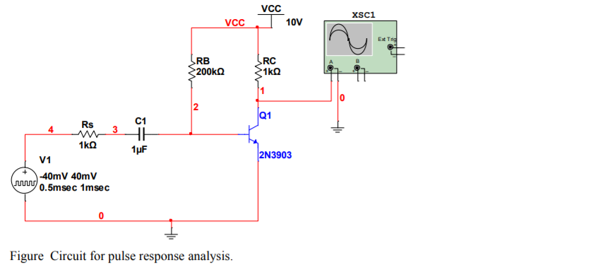
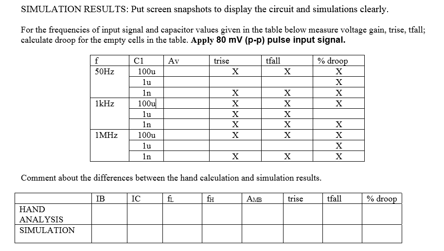
Fill the table pls VCC 10V xsci VCC Est Tng RB 200k RC 1kg 2 Q1 RS 4 3 C1 HH 1uF 2N3903 1k V1


Fill the table pls
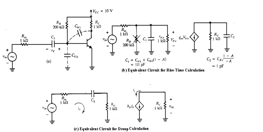
VCC 10V xsci VCC Est Tng RB 200k RC 1kg 2 Q1 RS 4 3 C1 HH 1uF 2N3903 1k V1 -40mV 40m V 0.5msec 1msec Figure Circuit for pulse response analysis. + === SPICE Model .MODEL 2N3903 NPN (Is=6.734f Xti=3 Eg=1.11 Vaf=74.03 Bf=335.2 Ne=1.208 Ise=6.734f Ikf=60.26m Xtb=1.5 Br=.8073 Nc=2 Isc=0 Ikr=0 Rc=1 Cjc=3.638p Mjc=.3085 Vjc=.75 Fc=.5 Cje=4.493p Mjer.2593 Vje-.75 Tr=243.9n Tf=300. 8p Itf=.4 Vtf=4 Xtf=2 Rb=10) + 9 Vec = 10 V RX 200 Co's RC IKO RE th . 1 Ro RE 1 C Bon Vie RA 200k 1 9 "1 - 1 G=C6c 1 - A -A (a) C = Cwe + Chill - A) - 111 pF 6) Equivalent Circuit for Rise-Time Calculation Rip iko CE RC Vce Vin IS2 (c) Equivalent Circuit for Droop Calculation SIMULATION RESULTS: Put screen snapshots to display the circuit and simulations clearly. For the frequencies of input signal and capacitor values given in the table below measure voltage gain, trise, tfall; calculate droop for the empty cells in the table. Apply 80 mV (p-p) pulse input signal. Av tfall f 50Hz trise X X % droop X X X X 1kHz ci 100u lu 1n 100u lu in 100u lu In X X X X X X X X X X 1 MHz X X X X X X Comment about the differences between the hand calculation and simulation results. IB IC fi fH AMB trise tfall % droop HAND ANALYSIS SIMULATION VCC 10V xsci VCC Est Tng RB 200k RC 1kg 2 Q1 RS 4 3 C1 HH 1uF 2N3903 1k V1 -40mV 40m V 0.5msec 1msec Figure Circuit for pulse response analysis. + === SPICE Model .MODEL 2N3903 NPN (Is=6.734f Xti=3 Eg=1.11 Vaf=74.03 Bf=335.2 Ne=1.208 Ise=6.734f Ikf=60.26m Xtb=1.5 Br=.8073 Nc=2 Isc=0 Ikr=0 Rc=1 Cjc=3.638p Mjc=.3085 Vjc=.75 Fc=.5 Cje=4.493p Mjer.2593 Vje-.75 Tr=243.9n Tf=300. 8p Itf=.4 Vtf=4 Xtf=2 Rb=10) + 9 Vec = 10 V RX 200 Co's RC IKO RE th . 1 Ro RE 1 C Bon Vie RA 200k 1 9 "1 - 1 G=C6c 1 - A -A (a) C = Cwe + Chill - A) - 111 pF 6) Equivalent Circuit for Rise-Time Calculation Rip iko CE RC Vce Vin IS2 (c) Equivalent Circuit for Droop Calculation SIMULATION RESULTS: Put screen snapshots to display the circuit and simulations clearly. For the frequencies of input signal and capacitor values given in the table below measure voltage gain, trise, tfall; calculate droop for the empty cells in the table. Apply 80 mV (p-p) pulse input signal. Av tfall f 50Hz trise X X % droop X X X X 1kHz ci 100u lu 1n 100u lu in 100u lu In X X X X X X X X X X 1 MHz X X X X X X Comment about the differences between the hand calculation and simulation results. IB IC fi fH AMB trise tfall % droop HAND ANALYSIS SIMULATIONStep by Step Solution
There are 3 Steps involved in it
Step: 1

Get Instant Access to Expert-Tailored Solutions
See step-by-step solutions with expert insights and AI powered tools for academic success
Step: 2

Step: 3

Ace Your Homework with AI
Get the answers you need in no time with our AI-driven, step-by-step assistance
Get Started


