

Question: Guys I need help with this experiment, Pleaseee TRANSISTOR AS SWITCH OBJECTIVE The purpose of the experiment is to design and analyze the operation of
Guys I need help with this experiment, Pleaseee
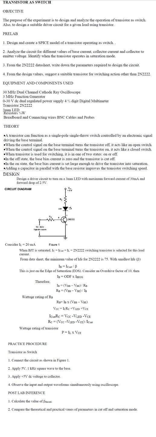
TRANSISTOR AS SWITCH OBJECTIVE The purpose of the experiment is to design and analyze the operation of transistor as switch Also, to design a suitable driver circuit for a given load using transistor. PRELAB 1. Design and create a SPICE model of a transistor operating as switch 2. Analyze the circuit for different values of base current collector current and collector to emitter voltage. Identify when the transistor operates in saturation mode. 3. From the 2N2222 datasheet, write down the parameters required to design the circuit. 4. From the design values, suggest a suitable transistor for switching action other than 2N2222. EQUIPMENT AND COMPONENTS USED 30 MHz Dual Channel Cathode Ray Oscilloscope 3 MHz Function Generator 0-30 V dc dual regulated power supply 4 y digit Digital Multimeter Transistor 2N2222 3mm LED Resistors WW Breadboard and Connecting wires BNC Cables and Probes THEORY A transistor can function as a single-pole single-throw switch controlled by an electronic signal driving the base terminal When the control signal on the base terminal turns the transistor off, it acts like an open switch. When the control signal on the base terminal turns the transistor on, it acts like a closed switch. When transistor is used for switching, it is in one of two states: on or off. In the off state, the base bias current is zero and the transistor is cut off. In the on state, the base bias current is set large enough to drive the transistor into saturation a capacitor in parallel with the base resistor improves the transistor switching speed. DESIGN Design a driver circuit to turn on a 3mm LED with maximum forward current of 30mA and forward drop of 2.5V. Adding a CIRCUIT DIAGRAM Vox 212222 SVIH se wave Consider IL = 20 mA Figure 1 When BJT is saturated. Ic = Icat= IL = 2N2222 switching transistor is selected for this load current From data sheet, the minimum value of hfe for 2N2222 is 75. With smallest hfe (B) Is = Icat/B This is just on the Edge of Saturation (EOS). Consider an Overdrive factor of 10, then 1s = ODF X IBEOS Therefore, IB = (VBB -VBE) / RB RB = (VBB-VBE) / 18 Wattage rating of RB Rg=18 x (VBB - VBE) Voc=IcRc + LED +VCE IcarRc = Vcc -VLED-VCE Rc = (Voc -VLED-VCE) /Icaat Wattage rating of transistor PEIL x VCE PRACTICE PROCEDURE Transistor as Switch 1. Connect the circuit as shown in Figure 1. 2. Apply SV. 1 kHz square wave to the base, 3. Apply +5V de voltage to collector 4. Observe the input and output waveforms simultaneously using oscilloscope. POST LAB INFERENCE 1. Calculate the value of forced 2. Compare the theoretical and practical vanes of parameters in cut off and saturation mode. TRANSISTOR AS SWITCH OBJECTIVE The purpose of the experiment is to design and analyze the operation of transistor as switch Also, to design a suitable driver circuit for a given load using transistor. PRELAB 1. Design and create a SPICE model of a transistor operating as switch 2. Analyze the circuit for different values of base current collector current and collector to emitter voltage. Identify when the transistor operates in saturation mode. 3. From the 2N2222 datasheet, write down the parameters required to design the circuit. 4. From the design values, suggest a suitable transistor for switching action other than 2N2222. EQUIPMENT AND COMPONENTS USED 30 MHz Dual Channel Cathode Ray Oscilloscope 3 MHz Function Generator 0-30 V dc dual regulated power supply 4 y digit Digital Multimeter Transistor 2N2222 3mm LED Resistors WW Breadboard and Connecting wires BNC Cables and Probes THEORY A transistor can function as a single-pole single-throw switch controlled by an electronic signal driving the base terminal When the control signal on the base terminal turns the transistor off, it acts like an open switch. When the control signal on the base terminal turns the transistor on, it acts like a closed switch. When transistor is used for switching, it is in one of two states: on or off. In the off state, the base bias current is zero and the transistor is cut off. In the on state, the base bias current is set large enough to drive the transistor into saturation a capacitor in parallel with the base resistor improves the transistor switching speed. DESIGN Design a driver circuit to turn on a 3mm LED with maximum forward current of 30mA and forward drop of 2.5V. Adding a CIRCUIT DIAGRAM Vox 212222 SVIH se wave Consider IL = 20 mA Figure 1 When BJT is saturated. Ic = Icat= IL = 2N2222 switching transistor is selected for this load current From data sheet, the minimum value of hfe for 2N2222 is 75. With smallest hfe (B) Is = Icat/B This is just on the Edge of Saturation (EOS). Consider an Overdrive factor of 10, then 1s = ODF X IBEOS Therefore, IB = (VBB -VBE) / RB RB = (VBB-VBE) / 18 Wattage rating of RB Rg=18 x (VBB - VBE) Voc=IcRc + LED +VCE IcarRc = Vcc -VLED-VCE Rc = (Voc -VLED-VCE) /Icaat Wattage rating of transistor PEIL x VCE PRACTICE PROCEDURE Transistor as Switch 1. Connect the circuit as shown in Figure 1. 2. Apply SV. 1 kHz square wave to the base, 3. Apply +5V de voltage to collector 4. Observe the input and output waveforms simultaneously using oscilloscope. POST LAB INFERENCE 1. Calculate the value of forced 2. Compare the theoretical and practical vanes of parameters in cut off and saturation mode
Step by Step Solution
There are 3 Steps involved in it

Get step-by-step solutions from verified subject matter experts