

Answered step by step
Verified Expert Solution
Question
1 Approved Answer
I need To make circuit Diagram in Logisim software So Please Help me with circuit diagram in Logisim software because I already ask question but
I need To make circuit Diagram in Logisim software So Please Help me with circuit diagram in Logisim software because I already ask question but it was not helpfull to me So Please help me with Circuit Diagram.
thank you!!
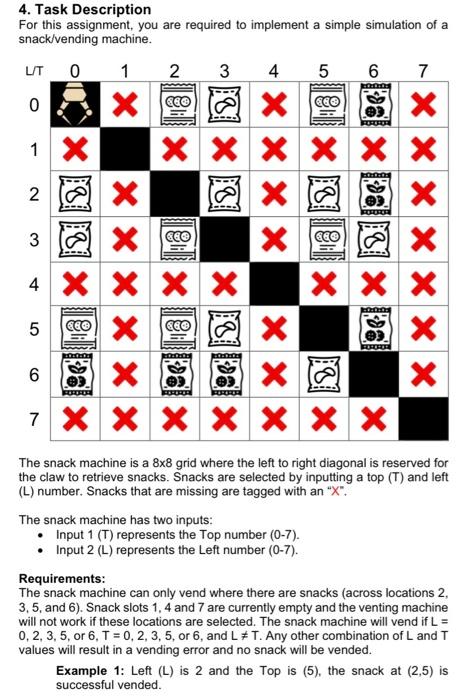
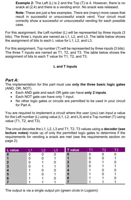
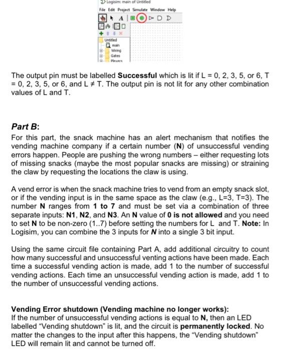
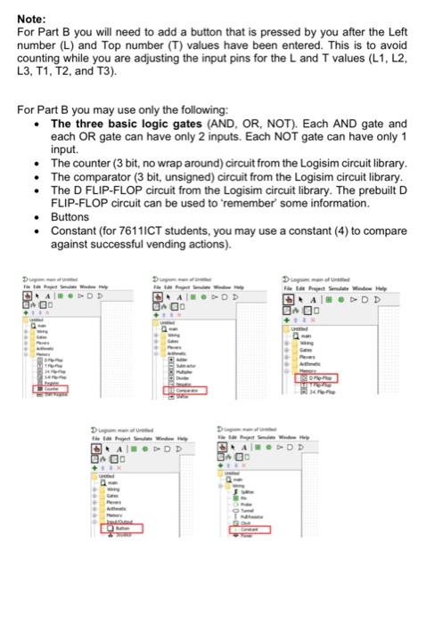
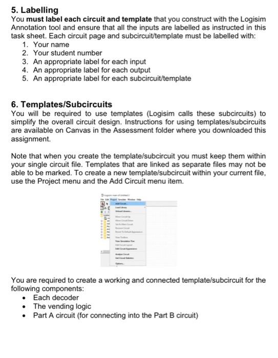
4. Task Description For this assignment, you are required to implement a simple simulation of a snack/vending machine. The snack machine is a 88 grid where the left to right diagonal is reserved for the claw to retrieve snacks. Snacks are selected by inputting a top (T) and left (L) number. Snacks that are missing are tagged with an " X ". The snack machine has two inputs: - Input 1(T) represents the Top number (0-7). - Input 2(L) represents the Left number (07). Requirements: The snack machine can only vend where there are snacks (across locations 2 , 3,5 , and 6). Snack slots 1, 4 and 7 are currently empty and the venting machine will not work if these locations are selected. The snack machine will vend if L= 0,2,3,5, or 6,T=0,2,3,5, or 6 , and L=T. Any other combination of L and T values will result in a vending error and no snack will be vended. Example 1: Left (L) is 2 and the Top is (5), the snack at (2,5) is successful vended. Example 2: The Left (L) is 2 and the Top (T) is 4. However, there is no snack at (2,4) and there is a vending error. No snack was released. Note: These are just a few examples. There are (many) more cases that result in successful or unsuccessful snack vend. Your circuit must correctly show a successful or unsuccessful vending for each possible case. For this assignment, the Left number (L) will be represented by three inputs ( 3 bits). The three L inputs are named as L1,L2, and L3. The table below shows the assignment of bits to each L value for L1, L2, and L3. For this assignment, Top number ( T ) will be represented by three inputs ( 3 bits). The three T inputs are named as T1,T2, and T3. The table below shows the assignment of bits to each T value for T1,T2, and T3. L and T Inputs Part A: The implementation for this part must use only the three basic logic gates (AND, OR, NOT). - Each AND gate and each OR gate can have only 2 inputs. - Each NOT gate can have only 1 input. - No other logic gates or circuits are permitted to be used in your circuit for Part A. You are required to implement a circuit where the user (you) can input a value for the Left number ( L) using value (L1, L2, and L3) and a Top number (T) using value (T1,T2, and T3). The circuit decodes the L1, L2, L3 and T1, T2, T3 values using a decoder (see lecture notes) made up of only the permitted logic gates to determine if the requirements for vending a snack are met (see the requirements section on page 2). The output is via a single output pin (green circle in Logisim): The output pin must be labelled Successful which is lit if L=0,2,3,5, or 6,T =0,2,3,5, or 6 , and L=T. The output pin is not lit for any other combination values of L and T. Part B: For this part, the snack machine has an alert mechanism that notifies the vending machine company if a certain number (N) of unsuccessful vending errors happen. People are pushing the wrong numbers - either requesting lots of missing snacks (maybe the most popular snacks are missing) or straining the claw by requesting the locations the claw is using. A vend error is when the snack machine tries to vend from an empty snack slot, or if the vending input is in the same space as the claw (e.g., L=3, T=3 ). The number N ranges from 1 to 7 and must be set via a combination of three separate inputs: N1, N2, and N3. An N value of O is not allowed and you need to set N to be non-zero (1..7) before setting the numbers for L and T. Note: In Logisim, you can combine the 3 inputs for N into a single 3 bit input. Using the same circuit file containing Part A, add additional circuitry to count how many successful and unsuccessful venting actions have been made. Each time a successful vending action is made, add 1 to the number of successful vending actions. Each time an unsuccessful vending action is made, add 1 to the number of unsuccessful vending actions. Vending Error shutdown (Vending machine no longer works): If the number of unsuccessful vending actions is equal to N, then an LED labelled "Vending shutdown" is lit, and the circuit is permanently locked. No matter the changes to the input after this happens, the "Vending shutdown" LED will remain lit and cannot be turned off. Note: For Part B you will need to add a button that is pressed by you after the Left number (L) and Top number (T) values have been entered. This is to avoid counting while you are adjusting the input pins for the L and T values (L1, L2, L3, T1, T2, and T3). For Part B you may use only the following: - The three basic logic gates (AND, OR, NOT). Each AND gate and each OR gate can have only 2 inputs. Each NOT gate can have only 1 input. - The counter (3 bit, no wrap around) circuit from the Logisim circuit library. - The comparator (3 bit, unsigned) circuit from the Logisim circuit library. - The D FLIP-FLOP circuit from the Logisim circuit library. The prebuilt D FLIP-FLOP circuit can be used to 'remember' some information. - Buttons - Constant (for 7611ICT students, you may use a constant (4) to compare against successful vending actions). 5. Labelling You must label each circuit and template that you construct with the Logisim Annotation tool and ensure that all the inputs are labelled as instructed in this task sheet. Each circuit page and subcircuittemplate must be labelled with: 1. Your name 2. Your student number 3. An appropriate label for each input 4. An appropriate label for each output 5. An appropriate label for each subcircuittemplate 6. Templates/Subcircuits You will be required to use templates (Logisim calls these subcircuits) to simplify the overall circuit design. Instructions for using templates/subcircuits are available on Canvas in the Assessment folder where you downloaded this assignment. Note that when you create the template/subcircuit you must keep them within your single circuit file. Templates that are linked as separate files may not be able to be marked. To create a new template/subcircuit within your current file, use the Project menu and the Add Circuit menu item. You are required to create a working and connected template/subcircuit for the following components: - Each decoder - The vending logic - Part A circuit (for connecting into the Part B circuit) Step by Step Solution
There are 3 Steps involved in it
Step: 1

Get Instant Access to Expert-Tailored Solutions
See step-by-step solutions with expert insights and AI powered tools for academic success
Step: 2

Step: 3
Ace Your Homework with AI
Get the answers you need in no time with our AI-driven, step-by-step assistance
Get Started
101 Database Exercises Text Workbook
Authors: McGraw-Hill
2nd Edition
0028007484, 978-0028007489