Question: Create two PLC ladder logic diagrams that use PLC coils and contacts to seal outputs. Then, you will use the Logix Pro simulation software to
Create two PLC ladder logic diagrams that use PLC coils and contacts to seal outputs. Then, you will use the Logix Pro simulation software to create the PLC ladder logic diagrams and verify their operation.


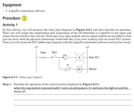
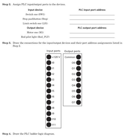
Equipment LogixPro simulation software Procedure Activity 1 In this activity, you will examine the relay logic diagram in Figure 6.5-1 and then describe its operation. Then, you will assign the input/output port connections of the I/O Simulator in LogixPro to the input and output devices listed in this activity. Drawings of an input module and an output module are provided so that you can draw what the physical connections would look like if you were working with an actual PLC system. Then, you will create the PLC ladder logic diagram with the LogixPro simulation software and test the circuit. L1 L2 Stop SW1 LS1 ** R M1 Red PLT Motor Figure 6.5-1--Relay Logic Diagram Step 1. Describe the operation of the control system displayed in Figure 6.5-1. when the stop button is pressed swith 1 turns on and powers LS1 and turns the light on and the motor off Step 2. Assign PLC input/output ports to the devices. Input device Switch one (SWI) Stop pushbutton (Stop) Limit switch one (LSD) Output device Motor one (M1) Red pilot light (Red PLT) Input ports +120 V Step 3. Draw the connections for the input/output devices and their port address assignments listed in Step 2. 10 11 12 13 14 15 16 17 18 19 110 111 Step 4. Draw the PLC ladder logic diagram. 2998 8 6 8 8 8 8 8 Output ports Common 01 02 03 04 05 PLC input port address 06 PLC output port address 07 Name, Step 5. Use the LogixPro simulation software to create the PLC ladder logic diagram. Step 6. Place the LogixPro simulation software online, download the PLC ladder logic diagram, and then place the software in run mode. Step 7. Demonstrate your working PLC system for your instructor. Approval:
Step by Step Solution
3.44 Rating (154 Votes )
There are 3 Steps involved in it

Get step-by-step solutions from verified subject matter experts


