

Question: In week 3, you were guided through creating a DHCP server on a Cisco router and implementing DNS in a network. In this and
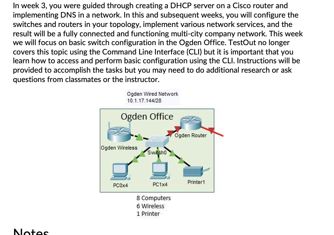
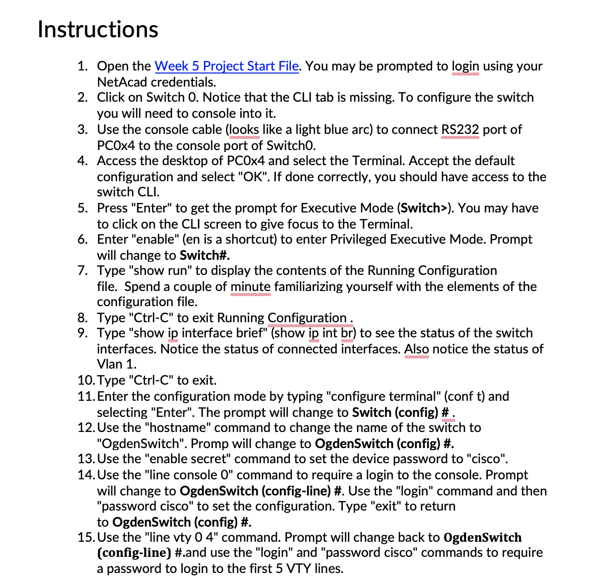
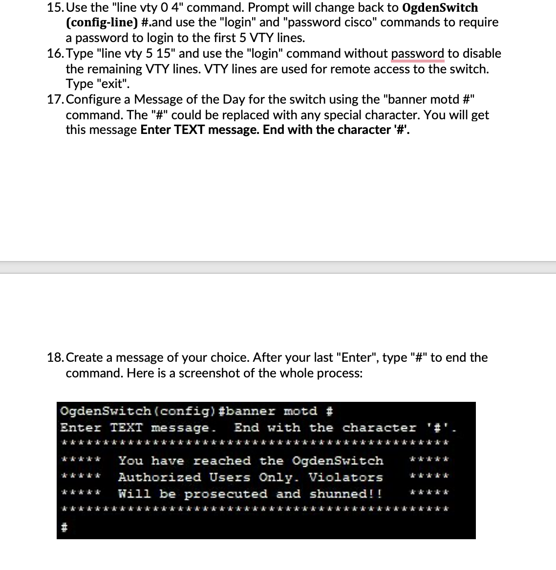
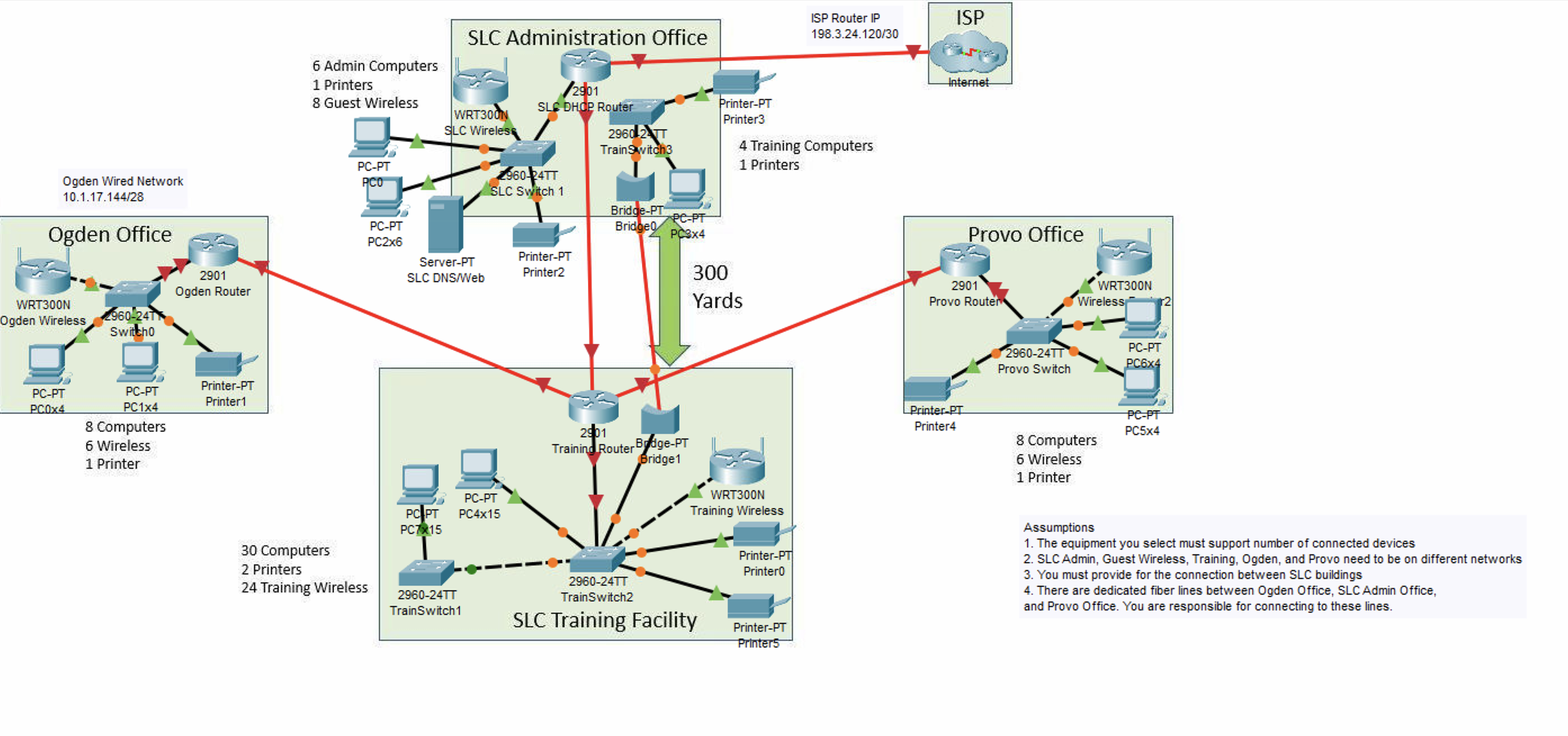
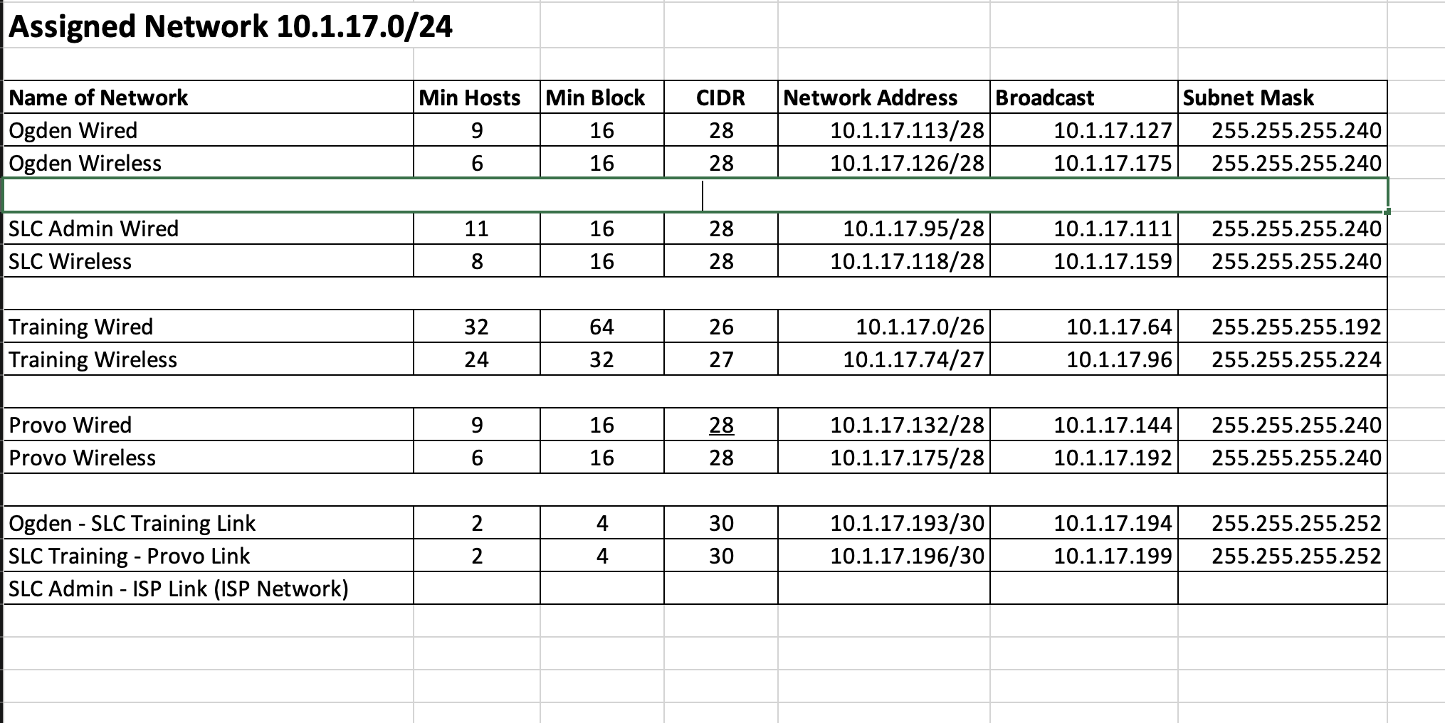
In week 3, you were guided through creating a DHCP server on a Cisco router and implementing DNS in a network. In this and subsequent weeks, you will configure the switches and routers in your topology, implement various network services, and the result will be a fully connected and functioning multi-city company network. This week we will focus on basic switch configuration in the Ogden Office. TestOut no longer covers this topic using the Command Line Interface (CLI) but it is important that you learn how to access and perform basic configuration using the CLI. Instructions will be provided to accomplish the tasks but you may need to do additional research or ask questions from classmates or the instructor. Notes Ogden Wired Network 10.1.17.144/28 Ogden Office Ogden Wireless PC0x4 Switcho PC1x4 8 Computers 6 Wireless 1 Printer Ogden Rou Printer1 Notes The 10.1.17.144/28 network has been assigned to the Ogden Office. This may be a different network than you selected in the Week 3 project. Passwords for all devices will be "cisco". This is not good practice but we will use this password for convenience. You will be working only on the switch in the Ogden Office. You don't need to configure anything on the router yet. If you would like to print the instructions, open and print the Instructions File. Instructions 1. Open the Week 5 Project Start File. You may be prompted to login using your NetAcad credentials. 2. Click on Switch O. Notice that the CLI tab is missing. To configure the switch you will need to console into it. 3. Use the console cable (looks like a light blue arc) to connect RS232 port of PC0x4 to the console port of Switch0. 4. Access the desktop of PC0x4 and select the Terminal. Accept the default configuration and select "OK". If done correctly, you should have access to the switch CLI. 5. Press "Enter" to get the prompt for Executive Mode (Switch>). You may have to click on the CLI screen to give focus to the Terminal. 6. Enter "enable" (en is a shortcut) to enter Privileged Executive Mode. Prompt will change to Switch#. 7. Type "show run" to display the contents of the Running Configuration file. Spend a couple of minute familiarizing yourself with the elements of the configuration file. 8. Type "Ctrl-C" to exit Running Configuration. 9. Type "show ip interface brief" (show ip int br) to see the status of the switch interfaces. Notice the status of connected interfaces. Also notice the status of Vlan 1. 10. Type "Ctrl-C" to exit. 11. Enter the configuration mode by typing "configure terminal" (conf t) and selecting "Enter". The prompt will change to Switch (config)# . 12. Use the "hostname" command to change the name of the switch to "OgdenSwitch". Promp will change to OgdenSwitch (config)#. 13. Use the "enable secret" command to set the device password to "cisco". 14. Use the "line console 0" command to require a login to the console. Prompt will change to OgdenSwitch (config-line) #. Use the "login" command and then "password cisco" to set the configuration. Type "exit" to return to OgdenSwitch (config) #. 15. Use the "line vty 0 4" command. Prompt will change back to OgdenSwitch (config-line) #.and use the "login" and "password cisco" commands to require a password to login to the first 5 VTY lines. 15. Use the "line vty 0 4" command. Prompt will change back to OgdenSwitch (config-line) #.and use the "login" and "password cisco" commands to require a password to login to the first 5 VTY lines. 16. Type "line vty 5 15" and use the "login" command without password to disable the remaining VTY lines. VTY lines are used for remote access to the switch. Type "exit". 17. Configure a Message of the Day for the switch using the "banner motd #" command. The "#" could be replaced with any special character. You will get this message Enter TEXT message. End with the character '#'. 18. Create a message of your choice. After your last "Enter", type "#" to end the command. Here is a screenshot of the whole process: OgdenSwitch (config) #banner motd # r TEXT message. kkkkkkk k k k k k k k k k k k k k k k k k k k k k Er &&&&& ***** You have reached the OgdenSwitch Authorized Users Only. Violators Will be prosecuted and shunned!! &&&&& & & A # End with the character '#' &&&&&* kkkkkkkkkkkkkk ***** &&&&& &&&&& kkkk 19. By default, the only way to communicate with a switch is using the console cable. Most network administrators would prefer to manage network devices remotely. In order to do this, you need to assign an IP address to the switch. This is done by configuring the VLAN1 interface. After completing the MOTD, the prompt should be OgdenSwitch (config) #. Type "interface VLAN1" and Enter. The prompt will change to OgdenSwitch (config-if) #. 20. Assign VLAN 1 the second address in the network (first is reserved for the router gateway). Type "ip address 10.1.17.146 255.255.255.240" and Enter. 21. From step 9, you should have noticed that VLAN 1 was administratively shut down. Enable the interface by typing "no shutdown" and Enter. 22. You should get a message the Interface Vlan1 is up. 23. At present, all the changes you have made are in the Running Configuration file. To save your changes, you need to copy the Running Configuration to the Start Configuration file. To do this, type "Ctrl-Z" to exit to Privileged Exec mode. Then type "copy run start" and accept the default name. Your switch is configured. 24. To test your configuration and confirm your switch is configured for remote management, configure PC1x4 with an IP address and subnet mask on the network. 25. From PC1x4 type "telnet 10.1.17.146" and Enter. If you've done everything right, you should have access to the Ogden Switch CLI. You should see the MOTD and have a password prompt. Log into the switch using the appropriate passwords. Once you enter Privileged Exec mode, take a screenshot of the command prompt window from the telnet command down to the Privileged Exec prompt. Ogden Wired Network 10.1.17.144/28 Ogden Office WRT300N Ogden Wireless 2960-24T Switcho PC-PT PC0x4 PC-PT PC1x4 8 Computers 6 Wireless 1 Printer 2901 Ogden Router Printer-PT Printer1 6 Admin Computers 1 Printers 8 Guest Wireless 1 PC-PT PCO D PC-PT PC2x6 30 Computers 2 Printers 24 Training Wireless PC PT PC7X15 SLC Administration Office WRT300N SLC Wireles Server-PT SLC DNS/Web 2960-24TT TrainSwitch1 PC-PT PC4x15 /2901 SL DHOP Router 1960-24TT SLC Switch 1 Printer-PT Printer2 2960-24TT TrainSwitch3 Bridge-PT Bridge 25 PC-PT PC3x4 2901 Training Router Bdge-PT Bridge1 Printer-PT Printer3 300 Yards 2960-24TT TrainSwitch2 SLC Training Facility 4 Training Computers 1 Printers WRT300N Training Wireless Printer-PT Printer0 ISP Router IP 198.3.24.120/30 Printer-PT Printers ISP Internet Provo Office 2901 Provo Router LPrinter-PT Printer4 2960-24TT Provo Switch WRT300N Wireless 8 Computers 6 Wireless 1 Printer PC-PT PC6x4 25 PC-PT PC5x4 Assumptions 1. The equipment you select must support number of connected devices 2. SLC Admin, Guest Wireless, Training, Ogden, and Provo need to be on different networks 3. You must provide for the connection between SLC buildings 4. There are dedicated fiber lines between Ogden Office, SLC Admin Office, and Provo Office. You are responsible for connecting to these lines. Assigned Network 10.1.17.0/24 Name of Network Ogden Wired Ogden Wireless SLC Admin Wired SLC Wireless Training Wired Training Wireless Provo Wired Provo Wireless Ogden - SLC Training Link SLC Training - Provo Link SLC Admin - ISP Link (ISP Network) Min Hosts 9 6 11 8 32 24 9 6 2 2 Min Block 16 16 16 16 64 32 16 16 4 4 CIDR 28 28 28 28 26 27 28 28 30 30 Network Address Broadcast 10.1.17.113/28 10.1.17.126/28 10.1.17.95/28 10.1.17.118/28 10.1.17.0/26 10.1.17.74/27 10.1.17.132/28 10.1.17.175/28 Subnet Mask 10.1.17.127 255.255.255.240 10.1.17.175 255.255.255.240 10.1.17.193/30 10.1.17.196/30 10.1.17.111 255.255.255.240 10.1.17.159 255.255.255.240 10.1.17.64 255.255.255.192 10.1.17.96 255.255.255.224 10.1.17.144 255.255.255.240 10.1.17.192 255.255.255.240 10.1.17.194 255.255.255.252 10.1.17.199 255.255.255.252
Step by Step Solution
There are 3 Steps involved in it
It seems like youre sharing a set of instructions and network details for configuring a Cisco switch ... View full answer

Get step-by-step solutions from verified subject matter experts