

Answered step by step
Verified Expert Solution
Question
1 Approved Answer
Just answer g and h unknown values just use parameters Question I (70%) Fig. 1 is a two stage amplifier with feedback. The source V,
Just answer g and h unknown values just use parameters
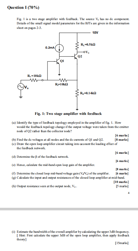
Question I (70%) Fig. 1 is a two stage amplifier with feedback. The source V, has no de component. Details of the small signal model parameters for the BJTs are given in the information sheet on pages 2-3. 10V R, -0.560 0.2mA OV, Q2 Q1 Ri=1002 R-1010 R=0,140 Fig. 1: Two stage amplifier with feedback (a) Identify the type of feedback topology employed in the amplifier of fig. 1. How would the feedback topology change if the output voltage were taken from the emitter node of Q2 rather than the collector node? [6 marks] (b) Find the de voltages at all nodes and the de currents of QI and Q2. [8 marks] (c) Draw the open loop amplifier circuit taking into account the loading effect of the feedback network [6 marks (d) Determine the of the feedback network. [6 marks] (e) Hence, calculate the mid-band open loop gain of the amplifier. [8 marks] (1) Determine the closed loop mid-band voltage gain (V/V.) of the amplifier. [6 marks] (g) Calculate the input and output resistances of the closed loop amplifier at mid-band. [10 marks) (h) Output resistance seen at the output node, V.. (5 marks) 4 (1) Estimate the bandwidth of the overall amplifier by calculating the upper 3dB frequency. [ Hint: First calculate the upper 3dB of the open loop amplifier, then apply feedback theory] [15marks) Question I (70%) Fig. 1 is a two stage amplifier with feedback. The source V, has no de component. Details of the small signal model parameters for the BJTs are given in the information sheet on pages 2-3. 10V R, -0.560 0.2mA OV, Q2 Q1 Ri=1002 R-1010 R=0,140 Fig. 1: Two stage amplifier with feedback (a) Identify the type of feedback topology employed in the amplifier of fig. 1. How would the feedback topology change if the output voltage were taken from the emitter node of Q2 rather than the collector node? [6 marks] (b) Find the de voltages at all nodes and the de currents of QI and Q2. [8 marks] (c) Draw the open loop amplifier circuit taking into account the loading effect of the feedback network [6 marks (d) Determine the of the feedback network. [6 marks] (e) Hence, calculate the mid-band open loop gain of the amplifier. [8 marks] (1) Determine the closed loop mid-band voltage gain (V/V.) of the amplifier. [6 marks] (g) Calculate the input and output resistances of the closed loop amplifier at mid-band. [10 marks) (h) Output resistance seen at the output node, V.. (5 marks) 4 (1) Estimate the bandwidth of the overall amplifier by calculating the upper 3dB frequency. [ Hint: First calculate the upper 3dB of the open loop amplifier, then apply feedback theory] [15marks)Step by Step Solution
There are 3 Steps involved in it
Step: 1

Get Instant Access to Expert-Tailored Solutions
See step-by-step solutions with expert insights and AI powered tools for academic success
Step: 2

Step: 3
Ace Your Homework with AI
Get the answers you need in no time with our AI-driven, step-by-step assistance
Get Started
Audit Committees Audit Committees Issues Constraints And Development Trends Of Their Roles And Responsibilities
Authors: Mounir Hedhili
1st Edition
620362120X, 978-6203621204