

Question: An RC circuit is shown in Figure 2. Assume that the voltage at the capacitor at t 0 is 0. (a) Find the system
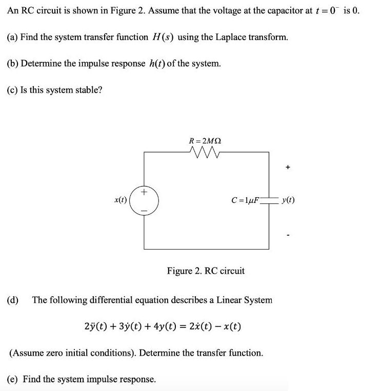
An RC circuit is shown in Figure 2. Assume that the voltage at the capacitor at t 0 is 0. (a) Find the system transfer function H(s) using the Laplace transform. (b) Determine the impulse response h(t) of the system. (c) Is this system stable? R = 2M2 x(t) C =lF y(t) Figure 2. RC circuit (d) The following differential equation describes a Linear System 2(t) + 3y(t) + 4y(t) = 2x(t)- x(t) (Assume zero initial conditions). Determine the transfer function. (e) Find the system impulse response.
Step by Step Solution
★★★★★
3.32 Rating (158 Votes )
There are 3 Steps involved in it
1 Expert Approved Answer
Step: 1 Unlock

Question Has Been Solved by an Expert!
Get step-by-step solutions from verified subject matter experts
Step: 2 Unlock
Step: 3 Unlock