Answered step by step
Verified Expert Solution
Question
1 Approved Answer
no lo pass the tests. nputs Illust be in order vertically and must face East. Outputs must be in order vertically and must face West.
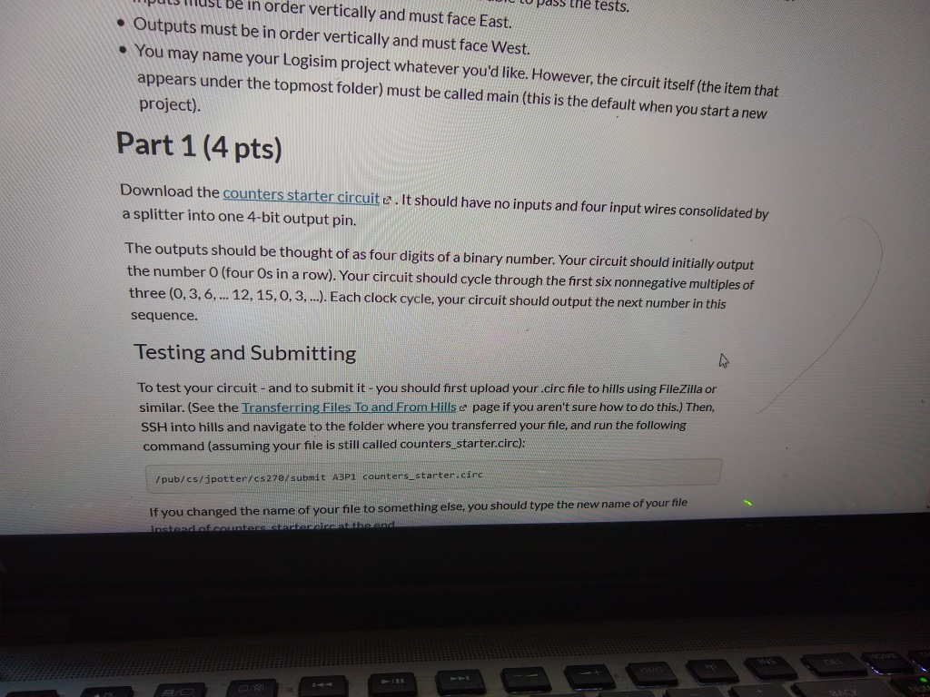
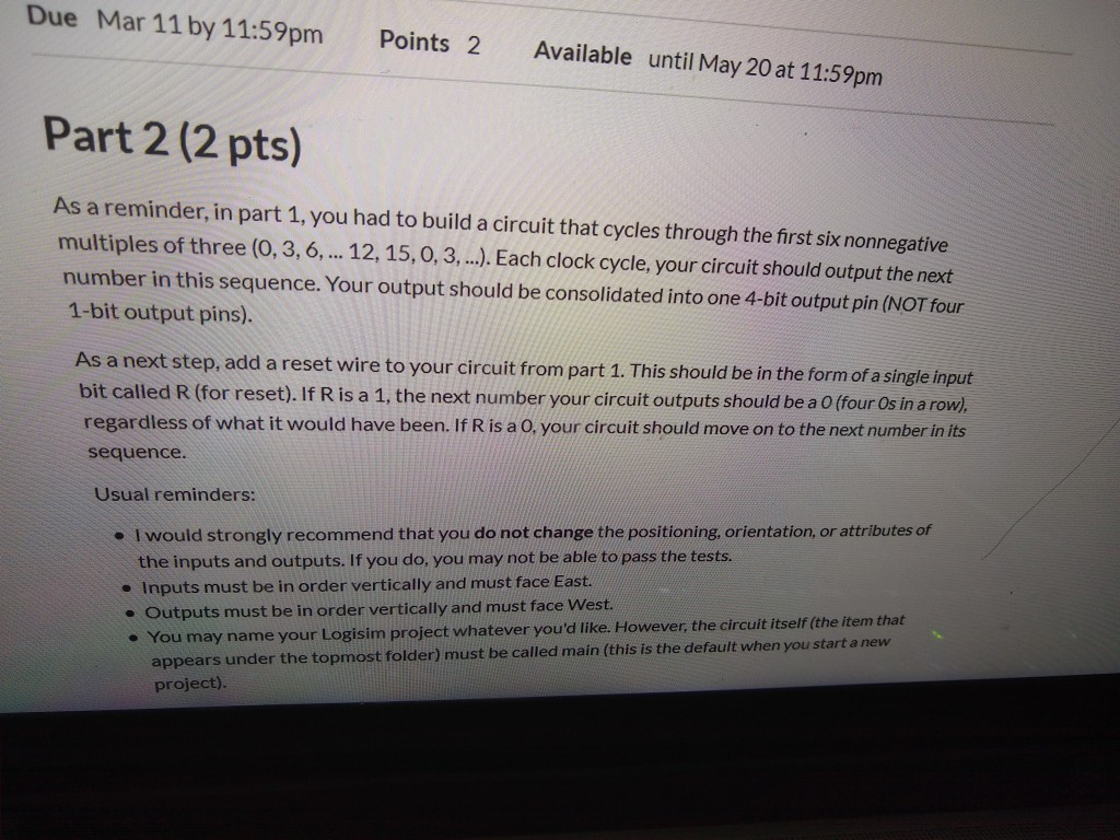
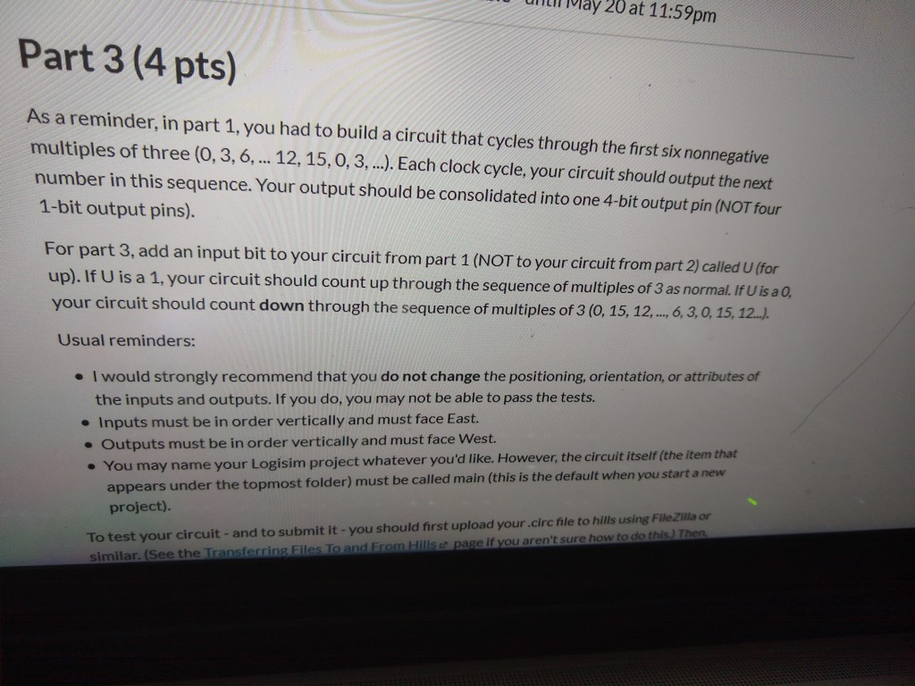
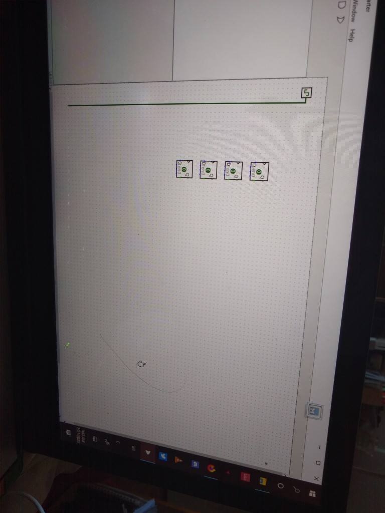
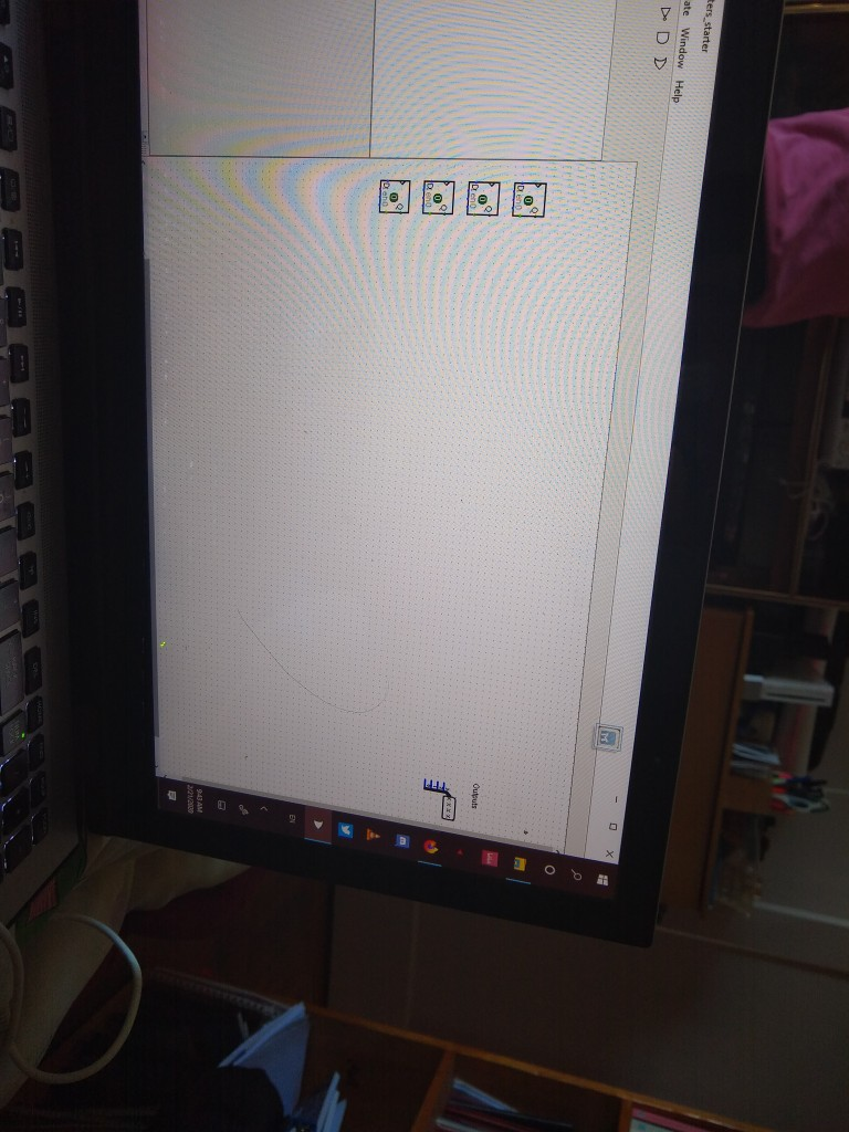
no lo pass the tests. nputs Illust be in order vertically and must face East. Outputs must be in order vertically and must face West. You may name your Logisim project whatever you'd like. However, the circuit itself (the item that appears under the topmost folder) must be called main(this is the default when you start a new project). Part 1 (4 pts) Download the counters starter circuite. It should have no inputs and four input wires consolidated by a splitter into one 4-bit output pin. The outputs should be thought of as four digits of a binary number. Your circuit should initially output the number 0 (four Os in a row). Your circuit should cycle through the first six nonnegative multiples of three (0,3, 6, ... 12, 15,0,3,...). Each clock cycle, your circuit should output the next number in this sequence. Testing and Submitting To test your circuit - and to submit it - you should first upload your.circfile to hills using FileZilla or similar. (See the Transferring Files To and From Hills e page if you aren't sure how to do this.) Then SSH into hills and navigate to the folder where you transferred your file, and run the following command (assuming your file is still called counters_starter.circ): /pub/cs/potter/cs27@/submit AP counters starter.cire If you changed the name of your file to something else, you should type the new name of your file instead of countersistent Due Mar 11 by 11:59pm Points 2 Available until May 20 at 11:59pm Part 2 (2 pts) As a reminder, in part 1, you had to build a circuit that cycles through the first six nonnegative multiples of three (0,3, 6, ... 12, 15, 0, 3, ...). Each clock cycle, your circuit should output the next number in this sequence. Your output should be consolidated into one 4-bit output pin (NOT four 1-bit output pins). As a next step, add a reset wire to your circuit from part 1. This should be in the form of a single input bit called R (for reset). If R is a 1, the next number your circuit outputs should be a 0 (four Os in a row). regardless of what it would have been. If R is a 0, your circuit should move on to the next number in its sequence. Usual reminders: . I would strongly recommend that you do not change the positioning, orientation, or attributes of the inputs and outputs. If you do, you may not be able to pass the tests. Inputs must be in order vertically and must face East. Outputs must be in order vertically and must face West. You may name your Logisim project whatever you'd like. However, the circuit itself (the item that appears under the topmost folder) must be called main (this is the default when you start a new project). UN May 20 at 11:59pm Part 3(4 pts) As a reminder, in part 1, you had to build a circuit that cycles through the first six nonnegative multiples of three (0, 3, 6, ... 12, 15, 0, 3, ...). Each clock cycle, your circuit should output the next number in this sequence. Your output should be consolidated into one 4-bit output pin (NOT four 1-bit output pins). For part 3, add an input bit to your circuit from part 1 (NOT to your circuit from part 2) called U (for up). If U is a 1, your circuit should count up through the sequence of multiples of 3 as normal. If U is a 0, your circuit should count down through the sequence of multiples of 3 (0, 15, 12,..., 6,3,0, 15, 12...). Usual reminders: . I would strongly recommend that you do not change the positioning, orientation, or attributes of the inputs and outputs. If you do, you may not be able to pass the tests. Inputs must be in order vertically and must face East. Outputs must be in order vertically and must face West. You may name your Logisim project whatever you'd like. However, the circuit itself (the item that appears under the topmost folder) must be called main (this is the default when you start a new project). To test your circuit - and to submit it - you should first upload your.circhle to hills using FileZilla or similar. (See the Transferring Files To and From Hills page if you aren't sure how to do this then arter Nindow Help ers starter ate Window Help ADD D20 no lo pass the tests. nputs Illust be in order vertically and must face East. Outputs must be in order vertically and must face West. You may name your Logisim project whatever you'd like. However, the circuit itself (the item that appears under the topmost folder) must be called main(this is the default when you start a new project). Part 1 (4 pts) Download the counters starter circuite. It should have no inputs and four input wires consolidated by a splitter into one 4-bit output pin. The outputs should be thought of as four digits of a binary number. Your circuit should initially output the number 0 (four Os in a row). Your circuit should cycle through the first six nonnegative multiples of three (0,3, 6, ... 12, 15,0,3,...). Each clock cycle, your circuit should output the next number in this sequence. Testing and Submitting To test your circuit - and to submit it - you should first upload your.circfile to hills using FileZilla or similar. (See the Transferring Files To and From Hills e page if you aren't sure how to do this.) Then SSH into hills and navigate to the folder where you transferred your file, and run the following command (assuming your file is still called counters_starter.circ): /pub/cs/potter/cs27@/submit AP counters starter.cire If you changed the name of your file to something else, you should type the new name of your file instead of countersistent Due Mar 11 by 11:59pm Points 2 Available until May 20 at 11:59pm Part 2 (2 pts) As a reminder, in part 1, you had to build a circuit that cycles through the first six nonnegative multiples of three (0,3, 6, ... 12, 15, 0, 3, ...). Each clock cycle, your circuit should output the next number in this sequence. Your output should be consolidated into one 4-bit output pin (NOT four 1-bit output pins). As a next step, add a reset wire to your circuit from part 1. This should be in the form of a single input bit called R (for reset). If R is a 1, the next number your circuit outputs should be a 0 (four Os in a row). regardless of what it would have been. If R is a 0, your circuit should move on to the next number in its sequence. Usual reminders: . I would strongly recommend that you do not change the positioning, orientation, or attributes of the inputs and outputs. If you do, you may not be able to pass the tests. Inputs must be in order vertically and must face East. Outputs must be in order vertically and must face West. You may name your Logisim project whatever you'd like. However, the circuit itself (the item that appears under the topmost folder) must be called main (this is the default when you start a new project). UN May 20 at 11:59pm Part 3(4 pts) As a reminder, in part 1, you had to build a circuit that cycles through the first six nonnegative multiples of three (0, 3, 6, ... 12, 15, 0, 3, ...). Each clock cycle, your circuit should output the next number in this sequence. Your output should be consolidated into one 4-bit output pin (NOT four 1-bit output pins). For part 3, add an input bit to your circuit from part 1 (NOT to your circuit from part 2) called U (for up). If U is a 1, your circuit should count up through the sequence of multiples of 3 as normal. If U is a 0, your circuit should count down through the sequence of multiples of 3 (0, 15, 12,..., 6,3,0, 15, 12...). Usual reminders: . I would strongly recommend that you do not change the positioning, orientation, or attributes of the inputs and outputs. If you do, you may not be able to pass the tests. Inputs must be in order vertically and must face East. Outputs must be in order vertically and must face West. You may name your Logisim project whatever you'd like. However, the circuit itself (the item that appears under the topmost folder) must be called main (this is the default when you start a new project). To test your circuit - and to submit it - you should first upload your.circhle to hills using FileZilla or similar. (See the Transferring Files To and From Hills page if you aren't sure how to do this then arter Nindow Help ers starter ate Window Help ADD D20
Step by Step Solution
There are 3 Steps involved in it
Step: 1

Get Instant Access to Expert-Tailored Solutions
See step-by-step solutions with expert insights and AI powered tools for academic success
Step: 2

Step: 3

Ace Your Homework with AI
Get the answers you need in no time with our AI-driven, step-by-step assistance
Get Started


