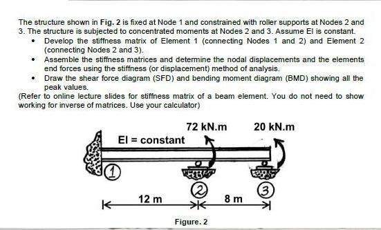
Question: The structure shown in Fig. 2 is fixed at Node 1 and constrained with roller supports at Nodes 2 and 3. The structure is

The structure shown in Fig. 2 is fixed at Node 1 and constrained with roller supports at Nodes 2 and 3. The structure is subjected to concentrated moments at Nodes 2 and 3. Assume El is constant. Develop the stiffness matrix of Element 1 (connecting Nodes 1 and 2) and Element 2 (connecting Nodes 2 and 3). Assemble the stiffness matrices and determine the nodal displacements and the elements end forces using the stiffness (or displacement) method of analysis. Draw the shear force diagram (SFD) and bending moment diagram (BMD) showing all the peak values. (Refer to online lecture slides for stiffness matrix of a beam element. You do not need to show working for inverse of matrices. Use your calculator) K 72 kN.m El = constant 12 m Figure. 2 8 m 20 kN.m (3
Step by Step Solution
3.43 Rating (159 Votes )
There are 3 Steps involved in it
The image provided shows a beam with a fixed support at Node 1 and roller supports at Nodes 2 and 3 The length between Node 1 and Node 2 is 12 meters and between Node 2 and Node 3 is 8 meters The exte... View full answer

Get step-by-step solutions from verified subject matter experts


