

Answered step by step
Verified Expert Solution
Question
1 Approved Answer
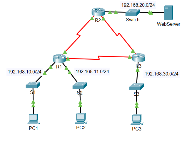
Packet Tracer - Configure Numbered Standard IPv 4 ACLs Addressing Table Objectives Part 1 : Plan an ACL Implementation Part 2 : Configure, Apply, and
Packet Tracer Configure Numbered Standard IPv ACLs Addressing Table
Objectives
Part : Plan an ACL Implementation
Part : Configure, Apply, and Verify a Standard ACL
Background Scenario
Device
Interface
R
G
IP Address
Subnet Mask
Default Gateway NA
G
S
S
R
G
NA
S
S
R
G
S
NA
S
PC
NIC
PC
NIC
PC
NIC
WebServer
NIC
Standard access control lists ACLs are router configuration scripts that control whether a router permits or denies packets based on the source address. This activity focuses on defining filtering criteria, configuring standard ACLs, applying ACLs to router interfaces, and verifying and testing the ACL implementation. The routers are already configured, including IP addresses and Enhanced Interior Gateway Routing Protocol EIGRP routing.
Instructions
Part : Plan an ACL Implementation
Step : Investigate the current network configuration.
Before applying any ACLs to a network, it is important to confirm that you have full connectivity. Verify that the network has full connectivity by choosing a PC and pinging other devices on the network. You should be able to successfully ping every device.
Step : Evaluate two network policies and plan ACL implementations.
a
The following network policies are implemented on R:
The network is not allowed access to the WebServer on the network. All other access is permitted.
To restrict access from the network to the Web Server at without interfering with other traffic, an ACL must be created on R The access list must be placed on the outbound interface to the WebServer. A second rule must be created on R to permit all other traffic.
b The following network policies are implemented on R:
The network is not allowed to communicate with the network. All other access is permitted.
To restrict access from the network to the network without interfering with other traffic, an access list will need to be created on R The ACL must be placed on the outbound interface to PC A second rule must be created on R to permit all other traffic. Part : Configure, Apply, and Verify a Standard ACL
Step : Configure and apply a numbered standard ACL on R
a Create an ACL using the number on R with a statement that denies access to the network from the network.
Rconfig# accesslist deny
b By default, an access list denies all traffic that does not match any rules. To permit all other traffic, configure the following statement:
Rconfig# accesslist permit any
c Before applying an access list to an interface to filter traffic, it is a best practice to review the contents of the access list, in order to verify that it will filter traffic as expected.
R# show accesslists
Standard IP access list
deny permit any
d For the ACL to actually filter traffic, it must be applied to some router operation. Apply the ACL by placing it for outbound traffic on the GigabitEthernet interface. Note: In an actual operational network, it is not a good practice to apply an untested access list to an active interface. Rconfig# interface GigabitEthernet
Rconfigif# ip accessgroup out
Step : Configure and apply a numbered standard ACL on R
a Create an ACL using the number on R with a statement that denies access to the network from the PC network.
Rconfig# accesslist deny
b By default, an ACL denies all traffic that does not match any rules. To permit all other traffic, create a second rule for ACL
Rconfig# accesslist permit any
c Verify that the access list is configured correctly.
R# show accesslists
Standard IP access list
deny
permit any
d Apply the ACL by placing it for outbound traffic on the GigabitEthernet interface.
Rconfig# interface GigabitEthernet
Rconfigif# ip accessgroup out
Step : Verify ACL configuration and functionality.
a Enter the show run or show ip interface gigabitethernet command to verify the ACL placements.
b With the two ACLs in place, network traffic is restricted according to the policies detailed in Part Use the following tests to verify the ACL implementations:
A ping from to succeeds.
A ping from to succeeds.
A ping from to
Step by Step Solution
There are 3 Steps involved in it
Step: 1

Get Instant Access to Expert-Tailored Solutions
See step-by-step solutions with expert insights and AI powered tools for academic success
Step: 2

Step: 3
Ace Your Homework with AI
Get the answers you need in no time with our AI-driven, step-by-step assistance
Get Started
Advances In Databases And Information Systems 25th European Conference Adbis 2021 Tartu Estonia August 24 26 2021 Proceedings Lncs 12843
Authors: Ladjel Bellatreche ,Marlon Dumas ,Panagiotis Karras ,Raimundas Matulevicius
1st Edition
3030824713, 978-3030824716