Answered step by step
Verified Expert Solution
Question
1 Approved Answer
Part 1 The switches are used to input logic levels to the gates. These switches are already appropriately connected to provide 1 and 0 .
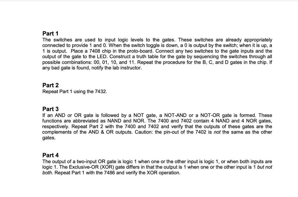
Part 1 The switches are used to input logic levels to the gates. These switches are already appropriately connected to provide 1 and 0 . When the switch toggle is down, a 0 is output by the switch; when it is up, a 1 is output. Place a 7408 chip in the proto-board. Connect any two switches to the gate inputs and the output of the gate to the LED. Construct a truth table for the gate by sequencing the switches through all possible combinations: 00,01,10, and 11. Repeat the procedure for the B,C, and D gates in the chip. If any bad gate is found, notify the lab instructor. Part 2 Repeat Part 1 using the 7432. Part 3 If an AND or OR gate is followed by a NOT gate, a NOT-AND or a NOT-OR gate is formed. These functions are abbreviated as NAND and NOR. The 7400 and 7402 contain 4 NAND and 4 NOR gates, respectively. Repeat Part 2 with the 7400 and 7402 and verify that the outputs of these gates are the complements of the AND \& OR outputs. Caution: the pin-out of the 7402 is not the same as the other gates. Part 4 The output of a two-input OR gate is logic 1 when one or the other input is logic 1 , or when both inputs are logic 1. The Exclusive-OR (XOR) gate differs in that the output is 1 when one or the other input is 1 but not both. Repeat Part 1 with the 7486 and verify the XOR operation
Step by Step Solution
There are 3 Steps involved in it
Step: 1
Get Instant Access to Expert-Tailored Solutions
See step-by-step solutions with expert insights and AI powered tools for academic success
Step: 2
Step: 3
Ace Your Homework with AI
Get the answers you need in no time with our AI-driven, step-by-step assistance
Get Started