

Question: Physics Online Lab Questions This is an online simulation to investigate relationships between voltage, current, resistance, and power for a simple circuit containing one resistor
Physics Online Lab Questions
This is an online simulation to investigate relationships between voltage, current, resistance, and power for a simple circuit containing one resistor and one battery. You will use a PhET simulation Circuit Construction Kit (DC) that allows you to build circuits using wires, resistors, batteries, and other circuit components.
Part A: Reference = Protocol (Instructions) below
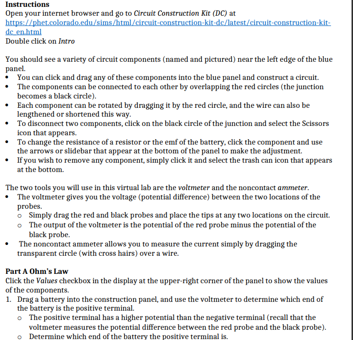
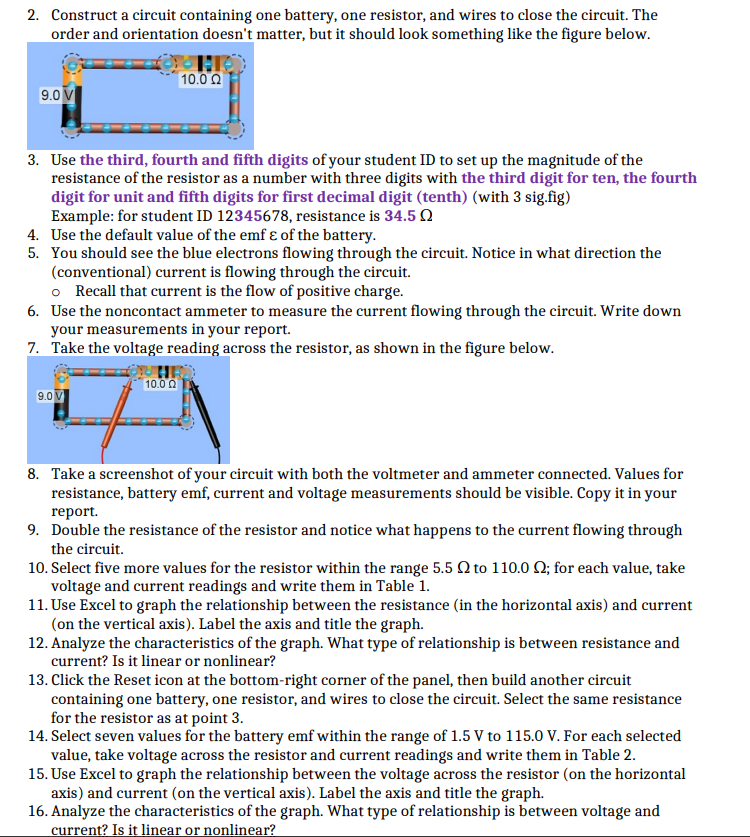
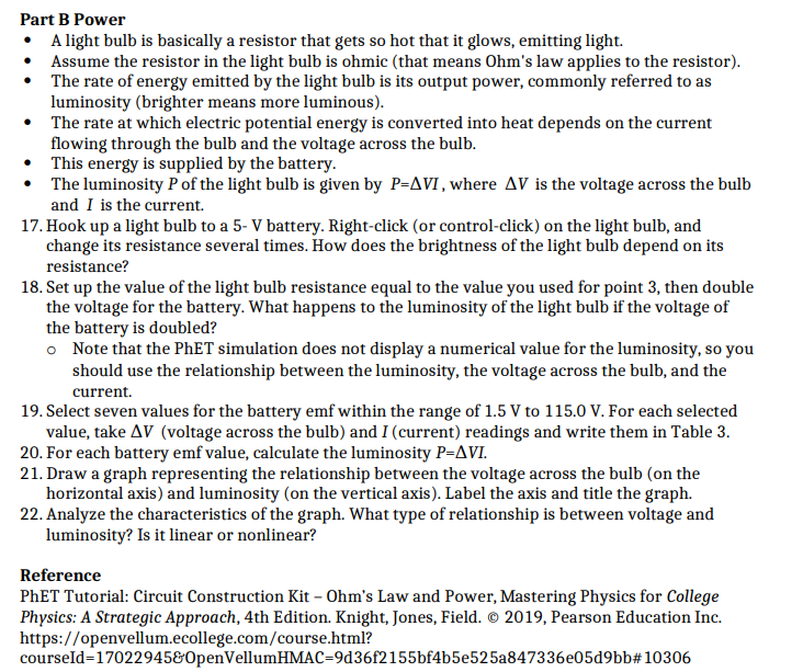
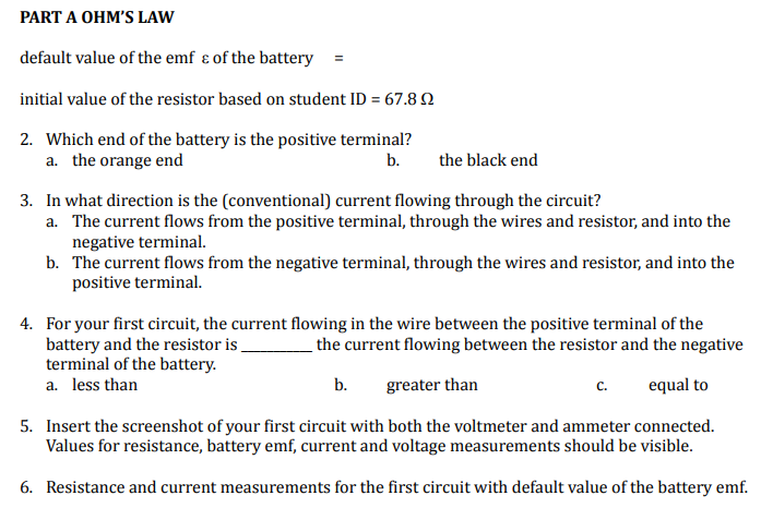

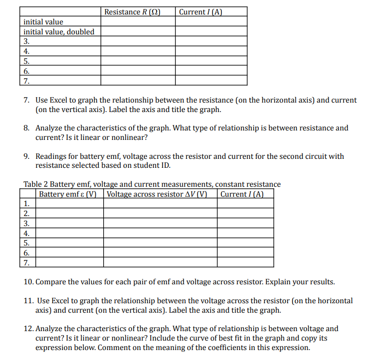
instructions Dpen your internet browser and go to Circuit Construction Kit {DC} at hit s: llet.t'uloradu.ctlu Sirnsflttm] cirt'uir-cunStrucliun-kil{It latest cit'cuit-cunatructiun-kil- dc Etthlml Double click on Intro You should see a variety of circuit components [named and pictured} near the left edge of the blue panel. ' You can click and drag any of these components into the blue panel and construct a circuit. I The components can be connected to each other by overlapping the red circles [thejunction becomes a black circle}. I Each component can be rotated by dragging it by the red circle, and the wire can also be lengthened or shortened this way. i To disconnect two components, click on the black circle of thejunction and select the Scissors icon that appears. Ir To change the resistance of a resistor or the emf of the battery, click the component and use the arrows or slid ebar that appear at the bottom of the panel to make the adjustment. I Ifyou wish to remove any component. simply click it and select the trash can icon that appears at the bottom. The two tools you will use in this virtual lab are the voltmeter and the noncontact ommeter. I! The voltmeter gives you the voltage {potential difference} between the two locations of the probes. o Simply drag the red and black probes and place the tips at any two locations on the circuit. o The output of the voltmeter is the potential of the red probe minus the potential of the black probe. Ir The noncontact ammeter allows you to measure the current simply by dragging the transparent circle [with cross hairs} over a wire. Part A Dhln's Law Click the Values checkbox in the display at the upper-right corner of the panel to show the values of the components. 1. Drag a battery into the construction panel, and use the voltmeter to determine which end of the battery is the positive terminal. o The positive terminal has a higher potential than the negative terminal {recall that the voltmeter measures the potential difference between the red probe and the black probe}. o Determine which end of the battery the positive terminal is. 2. Construct a circuit containing one battery, one resistor, and wires to close the circuit. The order and orientation doesn't matter, but it should look something like the figure below. 10.0 0 9.0 V 3. Use the third, fourth and fifth digits of your student ID to set up the magnitude of the resistance of the resistor as a number with three digits with the third digit for ten, the fourth digit for unit and fifth digits for first decimal digit (tenth) (with 3 sig.fig) Example: for student ID 12345678, resistance is 34.5 ( 4. Use the default value of the emf & of the battery. 5. You should see the blue electrons flowing through the circuit. Notice in what direction the (conventional) current is flowing through the circuit. o Recall that current is the flow of positive charge. 6. Use the noncontact ammeter to measure the current flowing through the circuit. Write down your measurements in your report. 7. Take the voltage reading across the resistor, as shown in the figure below. 10.0 0 9.0 V 8. Take a screenshot of your circuit with both the voltmeter and ammeter connected. Values for resistance, battery emf, current and voltage measurements should be visible. Copy it in your report. 9. Double the resistance of the resistor and notice what happens to the current flowing through the circuit. 10. Select five more values for the resistor within the range 5.5 0 to 110.0 0; for each value, take voltage and current readings and write them in Table 1. 1 1. Use Excel to graph the relationship between the resistance (in the horizontal axis) and current (on the vertical axis). Label the axis and title the graph. 12. Analyze the characteristics of the graph. What type of relationship is between resistance and current? Is it linear or nonlinear? 13. Click the Reset icon at the bottom-right corner of the panel, then build another circuit containing one battery, one resistor, and wires to close the circuit. Select the same resistance for the resistor as at point 3 14. Select seven values for the battery emf within the range of 1.5 V to 115.0 V. For each selected value, take voltage across the resistor and current readings and write them in Table 2. 15. Use Excel to graph the relationship between the voltage across the resistor (on the horizontal axis) and current (on the vertical axis). Label the axis and title the graph. 16. Analyze the characteristics of the graph. What type of relationship is between voltage and current? Is it linear or nonlinear?Part B Power It A. light bulb is basically a resistor that gets so hot that it glows, emitting light. . Assume the resistor in the light bulb is ohmic (that means Dhm's law applies to the resistor}. *- The rate of energy emitted by the light bulb is its output power, commonly referred to as luminosity (brighter means more luminous}. . The rate at which electric potential energy is converted into heat depends on the current flowing through the bulb and the voltage across the bulb. t This energy is supplied by the battery. . The luminosity P of the light bulb is given by P=VI , where av is the voltage across the bulb and I is the current. 1?. Hook up a light bulb to a 5- if battery. Right-click {or control-click] on the light bulb, and change its resistance several times. How does the brightness of the light bulb depend on its resistance? 13. Set up the value of the light bulb resistance equal to the value you used for point 3, then double the voltage for the battery. What happens to the luminosity of the light bulb if the voltage of the battery is doubled? o Note that the PhET simulation does not display a numerical value for the luminosity, so you should use the relationship between the luminosity, the voltage across the bulb, and the current. 19. Select seven values for the battery emf within the range of 1.5 V to 1 1512]| V. For each selected value, take Elli [voltage across the bulb] and I {current} readings and write them in Table 3. 20. For each battery emf value, calculate the luminosity 13:31.11 21. Draw a graph representing the relationship between the voltage across the bulb [on the horizontal axis} and luminosity [on the vertical axis}. Label the axis and title the graph. 22. Analyse the characteristics of the graph. What type of relationship is between voltage and luminosity? Is it linear or nonlinear? Reference PhET Tutorial: Circuit Construction Kit F hm's Law and Power, Mastering Physics for College Physics: A Strategic Approach, 4th Edition. Knight, Iones, Field. d1 2(119, Pearson Education Inc. htt ps: H o p envellume college.com fcourse.ht ml? courseld=1F22945tpenllellumHMAC=9d3Elf}!155bf4b5e525aBdTE 36eEd9bb# 11331116 PART A OHM'S LAW default value of the emf & of the battery = initial value of the resistor based on student ID = 67.8 0 2. Which end of the battery is the positive terminal? a. the orange end b. the black end 3. In what direction is the (conventional) current flowing through the circuit? a. The current flows from the positive terminal, through the wires and resistor, and into the negative terminal. b. The current flows from the negative terminal, through the wires and resistor, and into the positive terminal. 4. For your first circuit, the current flowing in the wire between the positive terminal of the battery and the resistor is the current flowing between the resistor and the negative terminal of the battery. a. less than b. greater than C. equal to 5. Insert the screenshot of your first circuit with both the voltmeter and ammeter connected. Values for resistance, battery emf, current and voltage measurements should be visible. 6. Resistance and current measurements for the first circuit with default value of the battery emf.Table 1 Resistance and current measurements, constant battery emfResistance R (Q) Current I (A) initial value initial value, doubled 3. 4. 5. 6. 7. 7. Use Excel to graph the relationship between the resistance (on the horizontal axis) and current (on the vertical axis). Label the axis and title the graph. 8. Analyze the characteristics of the graph. What type of relationship is between resistance and current? Is it linear or nonlinear? 9. Readings for battery emf, voltage across the resistor and current for the second circuit with resistance selected based on student ID. Table 2 Battery emf, voltage and current measurements, constant resistance Battery emf & (V) Voltage across resistor AV (V) Current / (A) 1. 2. 3. 4. 5. 6. 7. 10. Compare the values for each pair of emf and voltage across resistor. Explain your results. 11. Use Excel to graph the relationship between the voltage across the resistor (on the horizontal axis) and current (on the vertical axis). Label the axis and title the graph. 12. Analyze the characteristics of the graph. What type of relationship is between voltage and current? Is it linear or nonlinear? Include the curve of best fit in the graph and copy its expression below. Comment on the meaning of the coefficients in this expression
Step by Step Solution
There are 3 Steps involved in it

Get step-by-step solutions from verified subject matter experts