

Question: A common emitter BJT circuit is designed as shown in Figure. Determine the required values of V_CC,R_C and R_B. Assume that V_BE (on)=0.7 V.
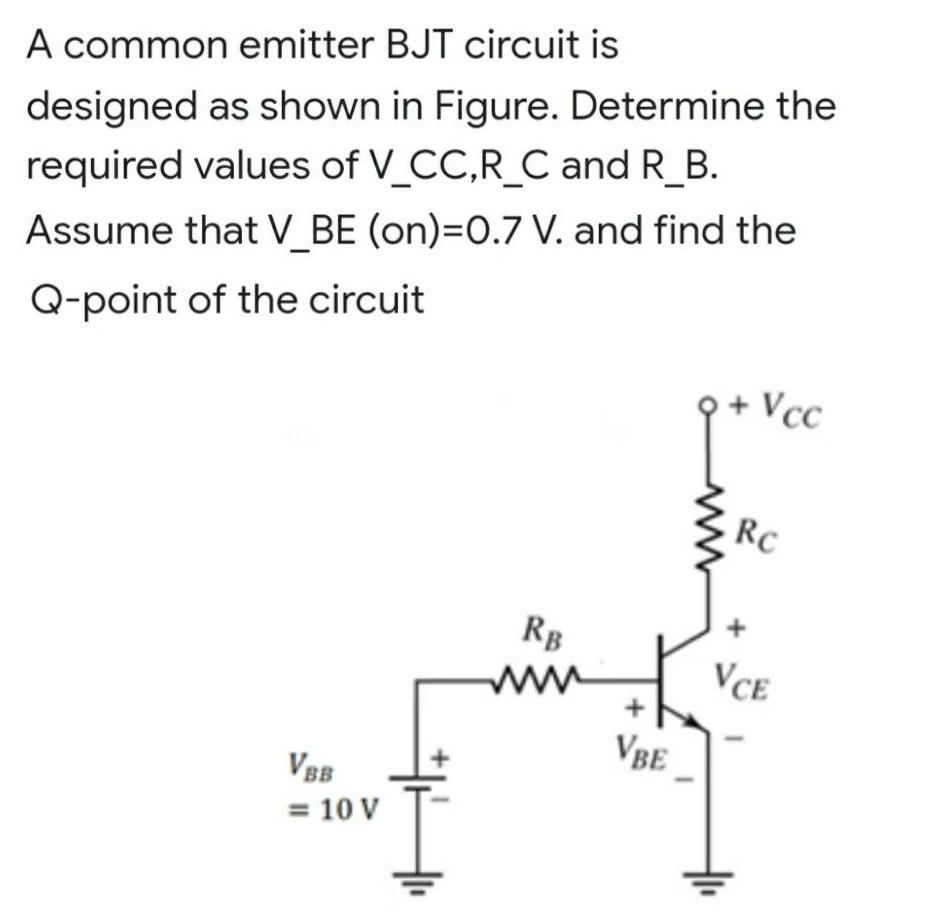
A common emitter BJT circuit is designed as shown in Figure. Determine the required values of V_CC,R_C and R_B. Assume that V_BE (on)=0.7 V. and find the Q-point of the circuit Vcc RC Rg ww VCE VBE VBB = 10 V
Step by Step Solution
★★★★★
3.51 Rating (158 Votes )
There are 3 Steps involved in it
1 Expert Approved Answer
Step: 1 Unlock

Question Has Been Solved by an Expert!
Get step-by-step solutions from verified subject matter experts
Step: 2 Unlock
Step: 3 Unlock
Document Format (2 attachments)
636382fc13247_238412.pdf
180 KBs PDF File
636382fc13247_238412.docx
120 KBs Word File