

619 A 33-F capacitor and a 10-mH inductor are connected in parallel with a closed switch as...
Question:
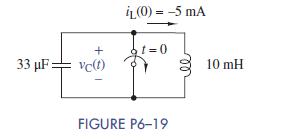
6–19 A 33-μF capacitor and a 10-mH inductor are connected in parallel with a closed switch as shown in Figure P6–19. The inductor has – 5mA flowing through it at t = 0– . The switch opens at t = 0:
(a) Find the initial voltage across the capacitor at t = 0.
(b) Write an equation for the voltage across the elements for t > 0. Do not solve it.
(c) Simulate the circuit using Multisim. Connect an inductor in parallel with a capacitor and assign the appropriate initial conditions and run a transient analysis. Plot the voltage across the elements for 5 ms.
(d) Characterize the response signal.
Step by Step Answer:

This question has not been answered yet.
You can Ask your question!
Related Book For 

The Analysis And Design Of Linear Circuits
ISBN: 9781119235385
8th Edition
Authors: Roland E. Thomas, Albert J. Rosa, Gregory J. Toussaint
Question Posted:
