

Question: Pipelined Datapath and Control The figure below shows the pipelined datapath with the control signals connected to the control portions of the pipeline registers. Consider
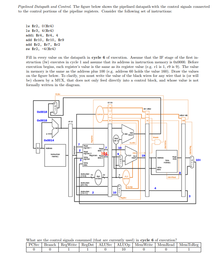
Pipelined Datapath and Control The figure below shows the pipelined datapath with the control signals connected to the control portions of the pipeline registers. Consider the following set of instructions: lw $r2, 0 ($r4) lw $r3, 4($r4) addi $r4, $r4, 4 add $r10, $r10, $r9 add $r2, $r7, $r2 Fill in every value on the datapath in cycle 6 of execution. Assume that the IF stage of the first in- struction (lw) executes in cycle 1 and assume that its address in instruction memory is 0x0000. Before execution begins, each register's value is the same as its register value (e.g. rl is 1, r9 is 9). The value in memory is the same as the address plus 100 (e.g. address 60 holds the value 160). Draw the values on the figure below. To clarify, you must write the value of the black wires for any wire that is (or will be) chosen by a MUX, that does not only feed directly into a control block, and whose value is not formally written in the diagram. ID EX ?? 0x0018 0x0018 0x0014 ragister 10 nghter 2 108 nstructian16 ALU 10 What are the control signals consumed (that are currently used) in cycle 6 of execution? PCSrc Branch RegWrite RegDst ALUSrc ALUOp MemWrite MemRead MemToReg 0 0 0 10 0 0 Pipelined Datapath and Control The figure below shows the pipelined datapath with the control signals connected to the control portions of the pipeline registers. Consider the following set of instructions: lw $r2, 0 ($r4) lw $r3, 4($r4) addi $r4, $r4, 4 add $r10, $r10, $r9 add $r2, $r7, $r2 Fill in every value on the datapath in cycle 6 of execution. Assume that the IF stage of the first in- struction (lw) executes in cycle 1 and assume that its address in instruction memory is 0x0000. Before execution begins, each register's value is the same as its register value (e.g. rl is 1, r9 is 9). The value in memory is the same as the address plus 100 (e.g. address 60 holds the value 160). Draw the values on the figure below. To clarify, you must write the value of the black wires for any wire that is (or will be) chosen by a MUX, that does not only feed directly into a control block, and whose value is not formally written in the diagram. ID EX ?? 0x0018 0x0018 0x0014 ragister 10 nghter 2 108 nstructian16 ALU 10 What are the control signals consumed (that are currently used) in cycle 6 of execution? PCSrc Branch RegWrite RegDst ALUSrc ALUOp MemWrite MemRead MemToReg 0 0 0 10 0 0
Step by Step Solution
There are 3 Steps involved in it

Get step-by-step solutions from verified subject matter experts