Answered step by step
Verified Expert Solution
Question
1 Approved Answer
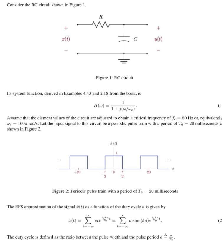
Consider the RC circuit shown in Figure 1. R z(t) C y(t) Figure 1: RC circuit. Its system function, derived in Examples 4.43 and


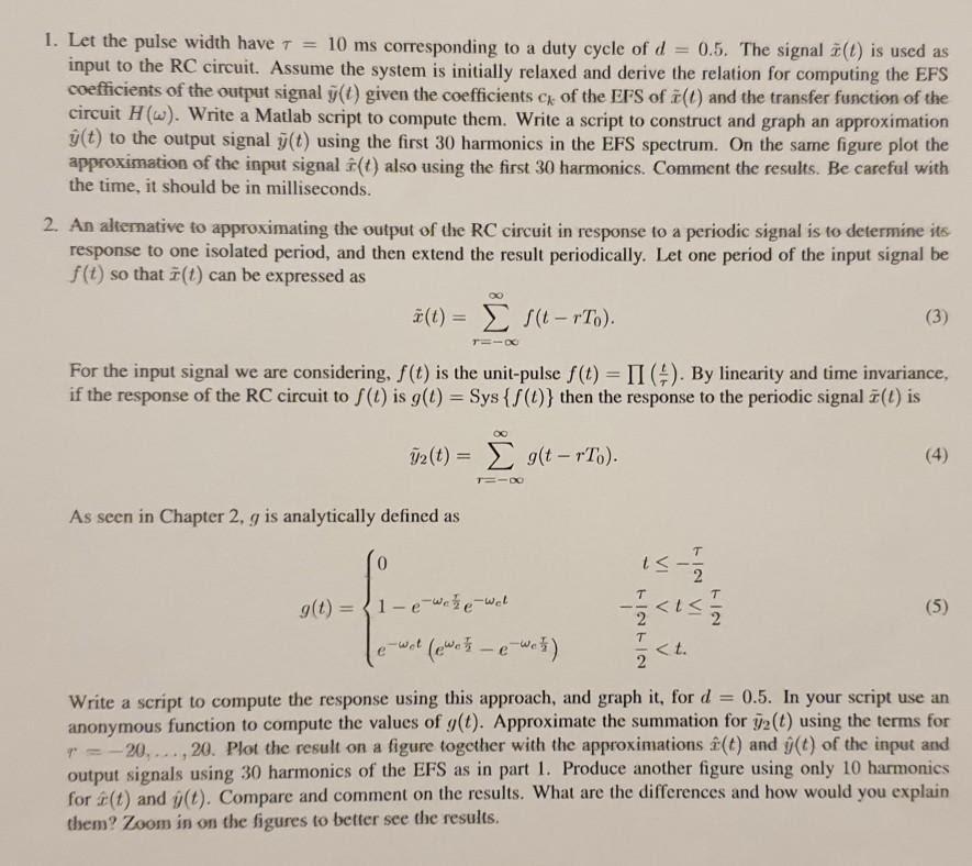
Consider the RC circuit shown in Figure 1. R z(t) C y(t) Figure 1: RC circuit. Its system function, derived in Examples 4.43 and 2.18 from the book, is 1 H(w) (1 1+ j(w/we)" Assume that the element values of the circuit are adjusted to obtain a critical frequency of fe = 80 Hz or, equivalently we = 160r rad/s. Let the input signal to this circuit be a periodic pulse train with a period of To = 20 milliseconds a shown in Figure 2. i (t) Figure 2: Periodic pulse train with a period of To = 20 milliseconds The EFS approximation of the signal F(t) as a function of the duty cycle d is given by (t) = Che o E d sinc(kd)eo k=- k=-00 The duty cycle is defined as the ratio between the pulse width and the pulse period d= 1. Let the pulse width have 7 = 10 ms corresponding to a duty cycle of d input to the RC circuit. Assume the system is initially relaxed and derive the relation for computing the EFS coefficients of the output signal g(t) given the coefficients c of the EFS of 7(t) and the transfer function of the circuit H(w). Write a Matlab script to compute them. Write a script to construct and graph an approximation y(t) to the output signal j(t) using the first 30 harmonics in the EFS spectrum. On the same figure plot the approximation of the input signal f(t) also using the first 30 harmonics. Comment the results. Be careful with the time, it should be in milliseconds. 0.5. The signal (t) is used as 2. An alternative to approximating the output of the RC circuit in response to a periodic signal is to determine its response to one isolated period, and then extend the result periodically. Let one period of the input signal be f(t) so that 7(t) can be expressed as #(t) = S(t - rTo). (3) %3D For the input signal we are considering, f(t) is the unit-pulse f(t) = II (). By linearity and time invariance, if the response of the RC circuit to f(t) is g(t) = Sys {f(t)} then the response to the periodie signal 7(t) is 2 (t) = 9(t - rTo). (4) %3D As seen in Chapter 2, g is analytically defined as g(t) ={1-e-wee-Wet (5) %3D 2 < t. 2 ewet Write a script to compute the response using this approach, and graph it, for d = anonymous function to compute the values of g(t). Approximate the summation for 2(t) using the terms for r = - 20,..., 20. Plot the result on a figure together with the approximations &(t) and g(t) of the input and output signals using 30 harmonics of the EFS as in part 1. Produce another figure using only 10 harmonics for (t) and j(t). Compare and comment on the results. What are the differences and how would you explain them? Zoom in on the figures to better see the results. 0.5. In your script use an
Step by Step Solution
★★★★★
3.49 Rating (159 Votes )
There are 3 Steps involved in it
Step: 1

Get Instant Access to Expert-Tailored Solutions
See step-by-step solutions with expert insights and AI powered tools for academic success
Step: 2

Step: 3

Ace Your Homework with AI
Get the answers you need in no time with our AI-driven, step-by-step assistance
Get Started


