

Question: Problem 2B.15. Shell momentum balances and pressure distribution for flow through a circular tube. In example 2.3, only the z momentum balance was derived. Answer
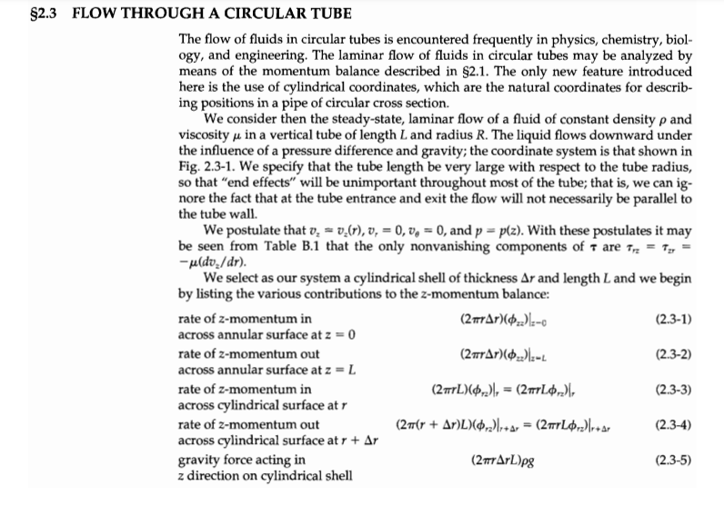
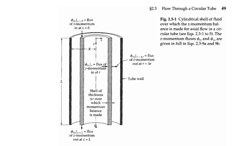
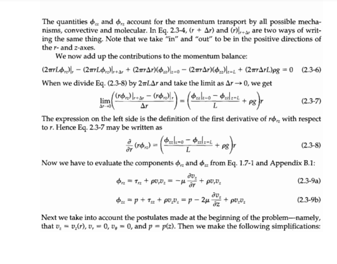
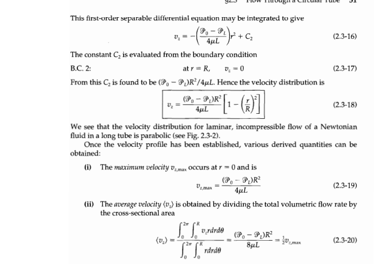
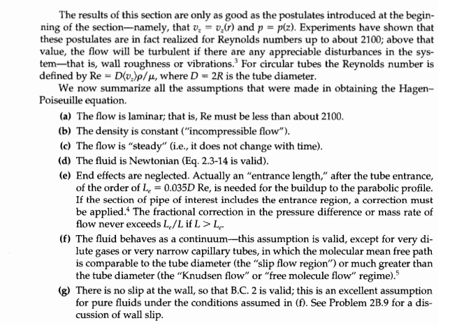
Problem 2B.15. Shell momentum balances and pressure distribution for flow through a circular tube. In example 2.3, only the z momentum balance was derived. Answer the following questions. a. Derive the r-component of the momentum balance using an approach that is similar to the one used to derive the z-component. b. Next, solve the resulting equations to derive an expression for the fluid pressure distribution in the tube as a function of the r and z coordinates. Why is the 6 component not required? $2.3 FLOW THROUGH A CIRCULAR TUBE The flow of fluids in circular tubes is encountered frequently in physics, chemistry, biol- ogy, and engineering. The laminar flow of fluids in circular tubes may be analyzed by means of the momentum balance described in $2.1. The only new feature introduced here is the use of cylindrical coordinates, which are the natural coordinates for describ- ing positions in a pipe of circular cross section. We consider then the steady-state, laminar flow of a fluid of constant density p and viscosity u in a vertical tube of length Land radius R. The liquid flows downward under the influence of a pressure difference and gravity; the coordinate system is that shown in Fig. 2.3-1. We specify that the tube length be very large with respect to the tube radius, so that end effects" will be unimportant throughout most of the tube; that is, we can ig- nore the fact that at the tube entrance and exit the flow will not necessarily be parallel to the tube wall. We postulate that v. = v-(), , = 0,06 = 0, and p = plz). With these postulates it may be seen from Table B.1 that the only nonvanishing components of 7 are Trz = Ty -uldv./dr). We select as our system a cylindrical shell of thickness Ar and length L and we begin by listing the various contributions to the z-momentum balance: rate of 2-momentum in (28Ar)(02).-6 (2.3-1) across annular surface at z = 0 rate of z-momentum out (2#Ar)(02):- (2.3-2) across annular surface at z = L rate of z-momentum in (29rL).), = (2010), (2.3-3) across cylindrical surface at rate of z-momentum out (277(r + Ar)L)(0,2),+Ar = (2+Lr)rtar (2.3-4) across cylindrical surface at r + Ar gravity force acting in ( 2ArL)pg (2.3-5) z direction on cylindrical shell 0212-0flux of z-momentum in at z = 0 $2.3 Flow Through a Circular Tube 49 Fig. 2.3-1 Cylindrical shell of fluid over which the z-momentum bal- ance is made for axial flow in a cir- cular tube (see Eqs. 2.3-1 to 5). The z-momentum fluxes dr and are given in full in Eqs. 2.3-9a and 9b. Orzltar - flux of z-momentum out at r + Ar l-flux of z-momentum in at -Tube wall L Shell of thickness Ar over which momentum balance is made Oulz-L = flux of z-momentum out at z = 2 lim = (10.),) (Mako 1-0 + pg) The quantities and Mrz account for the momentum transport by all possible mecha- nisms, convective and molecular. In Eq. 2.3-4, (r + Ar) and (r) + are two ways of writ- ing the same thing. Note that we take "in" and "out" to be in the positive directions of the r- and z-axes. We now add up the contributions to the momentum balance: (27102), (29Ln)\+ar+ (2#Ar)(02)}z=o (277Ar)(02)}z=+ (277ArL)pg = 0 (2.3-6) When we divide Eq. (2.3-8) by 2nLAr and take the limit as Ar 0, we get (rr2),+Ar -(02)) (ozak-e - zlz- (2.3-7) Ar L The expression on the left side is the definition of the first derivative of rrz with respect tor. Hence Eq. 2.3-7 may be written as -- + (2.3-8) ar L Now we have to evaluate the components on and , from Eq. 1.7-1 and Appendix B.1: dra Trz+pU,V2 - 4 r + pu,v: (2.3-9a) . $x = p + 12 + pu.v. = p - 2 (2.3-95) z Next we take into account the postulates made at the beginning of the problem-namely, that v, = v.(r), v, = 0, 0, = 0, and p = plz). Then we make the following simplifications: . (rou) = (Salmo Plot + ps); du. + puu: (7.) = (* = ps2)-(*%), 1 21 (i) because v, = 0, we can drop the term pov, in Eq. 2.3-9a; (ii) because v. = v.(r), the term po.v. will be the same at both ends of the tube; and (iii) because v. = v.(r), the term -2p0v./z will be the same at both ends of the tube. Hence Eq. 2.3-8 simplifies to (Po-P80) (P2 - PgL) (2.3-10) L in which P = p - Pgz is a convenient abbreviation for the sum of the pressure and gravi- tational terms.' Equation 2.3-10 may be integrated to give (9,- C (2.3-11) The constant C, is evaluated by using the boundary condition B.C. 1: at r = 0, Tr=finite (2.3-12) Consequently C, must be zero, for otherwise the momentum flux would be infinite at the axis of the tube. Therefore the momentum flux distribution is P TR = *22") (2.3-13) 2L This distribution is shown in Fig. 2.3-2. Newton's law of viscosity for this situation is obtained from Appendix B.2 as follows: du, (2.3-14) T2 - Mar Substitution of this expression into Eq. 2.3-13 then gives the following differential equa- tion for the velocity: du, dr P.-P. 2uL (2.3-15) =0 Parabolic velocity distribution vor Vz, max Tr2 = 0 Linear momentum flux distribution Trz(r) Trz, max (9,-)R 2L Fig. 2.3-2 The momentum-flux distribution and velocity distribu- tion for the downward flow in a circular tube The quantity designated by P is called the modified pressure. In general it is defined by P = p + pg, where h is the distance "upward"that is, in the direction opposed to gravity from some preselected reference plane. Hence in this problem h = -2. --(2,2%)x+ + C2 V. = 0 2)R?[1-(K)] This first-order separable differential equation may be integrated to give P.-P V, 4uL (2.3-16) The constant C, is evaluated from the boundary condition B.C. 2: at r = R (2.3-17) From this C is found to be (P. P.)R?/4uL. Hence the velocity distribution is (P, - PR Vz 4uL (2.3-18) We see that the velocity distribution for laminar, incompressible flow of a Newtonian fluid in a long tube is parabolic (see Fig. 2.3-2). Once the velocity profile has been established, various derived quantities can be obtained: (i) The maximum velocity 0z,max occurs at r = 0 and is (P.-P.R? (2.3-19) 4uL (ii) The average velocity (v.) is obtained by dividing the total volumetric flow rate by the cross-sectional area L" S* v.drde (P. - PR (v.) (2.3-20) 8 rdrde Uz_max '27 R 0 - 2 (iii) The mass rate of flow w is the product of the cross-sectional area R, the density p, and the average velocity (v.) T-(P, -P)Rp (2.3-21) 8L This rather famous result is called the Hagen-Poiseuille equation. It is used, along with experimental data for the rate of flow and the modified pressure difference, to determine the viscosity of fluids (see Example 2.3-1) in a "capillary viscometer." (iv) The z-component of the force, F,, of the fluid on the wetted surface of the pipe is just the shear stress Trz integrated over the wetted area do TR?(90 - 9) dr TR(Po - P + TRLpg (2.3-22) This result states that the viscous force F, is counterbalanced by the net pres- sure force and the gravitational force. This is exactly what one would obtain from making a force balance over the fluid in the tube. F:= mit (2#RLY( - )... - The results of this section are only as good as the postulates introduced at the begin- ning of the section--namely, that v, = v.(r) and p = p(z). Experiments have shown that these postulates are in fact realized for Reynolds numbers up to about 2100; above that value, the flow will be turbulent if there are any appreciable disturbances in the sys- temthat is, wall roughness or vibrations. For circular tubes the Reynolds number is defined by Re = D(v.)p/, where D = 2R is the tube diameter. We now summarize all the assumptions that were made in obtaining the Hagen- Poiseuille equation (a) The flow is laminar; that is, Re must be less than about 2100. (b) The density is constant ("incompressible flow"). (c) The flow is "steady" (i.e., it does not change with time). (d) The fluid is Newtonian (Eq. 2.3-14 is valid). (e) End effects are neglected. Actually an "entrance length," after the tube entrance, of the order of Le = 0.035D Re, is needed for the buildup to the parabolic profile. If the section of pipe of interest includes the entrance region, a correction must be applied. The fractional correction in the pressure difference or mass rate of flow never exceeds L/L if L > Le (f) The fluid behaves as a continuum--this assumption is valid, except for very di- lute gases or very narrow capillary tubes, in which the molecular mean free path is comparable to the tube diameter (the "slip flow region") or much greater than the tube diameter (the "Knudsen flow" or "free molecule flow" regime). (g) There is no slip at the wall, so that B.C. 2 is valid; this is an excellent assumption for pure fluids under the conditions assumed in (f). See Problem 2B.9 for a dis- cussion of wall slip
Step by Step Solution
There are 3 Steps involved in it

Get step-by-step solutions from verified subject matter experts