Question
Question 1. In homework 2 you implemented a machine that would produce the mod 3 output for an input stream of bits representing a binary
Question 1. In homework 2 you implemented a machine that would produce the mod 3 output for an input stream of bits representing a binary value. As part of that assignment you were asked to think about how the machine would return to the initial state once the completed binary value was provided.
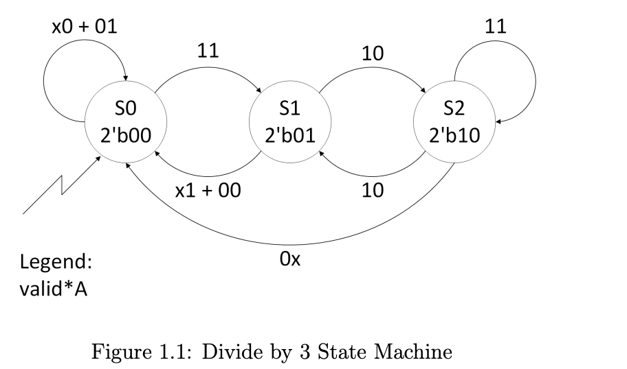
Once possible solution is to have a valid signal that comes along side the bits of input. The idea is that the machine will move through appropriate states based on the input so long as the valid signal is asserted. Once the valid signal is de-asserted then the machine would return to the initial state.
A state diagram for this functionality can be seen below. Notice the legend, the 2-bit quantities on the arcs represent the value of valid followed by the value of A. E.g. 10 means that valid is high and A is low, and x0 means that valid is dont care (could be zero or one) and that A is low. Where + is used it means the logical OR.

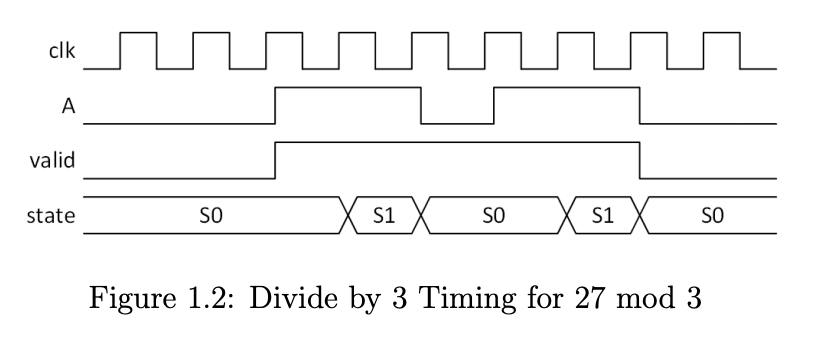
A timing diagram for the same case from homework 2 is shown below.
(a) Recall the following state assignment . . .
S0 = 2b00
S1 = 2b01
S2 = 2b10

(b) Draw out a timing diagram that shows the timing for 14 mod 3.
(c) Create simplified equations for the next state logic. Since there is no fourth state, use dont care for the next state when the current state is
2b11 irrespective of the inputs.
*See Part 2 for d&e
Figure 1.1: Divide by 3 State Machine Figure 1.2: Divide by 3 Timing for 27mod3
Step by Step Solution
There are 3 Steps involved in it
Step: 1

Get Instant Access to Expert-Tailored Solutions
See step-by-step solutions with expert insights and AI powered tools for academic success
Step: 2

Step: 3

Ace Your Homework with AI
Get the answers you need in no time with our AI-driven, step-by-step assistance
Get Started


